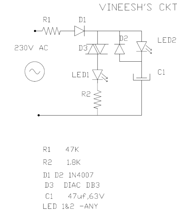
The following triac/diac based mains operated LED flasher circuit which is actually an astable multivibrator circuit utilizes only a diac and resistor arrangement for implementing interesting wig wag flashing of two LEDs. The simple 220V flasher circuit was shared with me by Mr.Vineesh, who is one of the keen followers of this blog. I would […]
Triac
SCR and Triac Gate Resistor Calculator

Here is a SCR and Triac gate resistor calculator along with the full detailed explanation. This will help users to calculate the right value of gate resistor for triggering an SCR or TRIAC safely. Calculator by homemade-circuits.com SCR / TRIAC Gate Resistor Calculator Gate Trigger Voltage (Vgt): Gate Trigger Current (Igt): Trigger Supply Voltage (Vs): […]
How To Use Triac For AC Power Control

Here we are talking about controlling things like lamps, motors, heaters, and other similar electrical loads. The devices we use for this purpose are called thyristor and triac, OK? Both these devices, thyristor and triac, they can actually do this job like simple switch ON/OFF or they can also adjust the power given to these […]
SCR/Triac Controlled Automatic Voltage Stabilizer Circuit
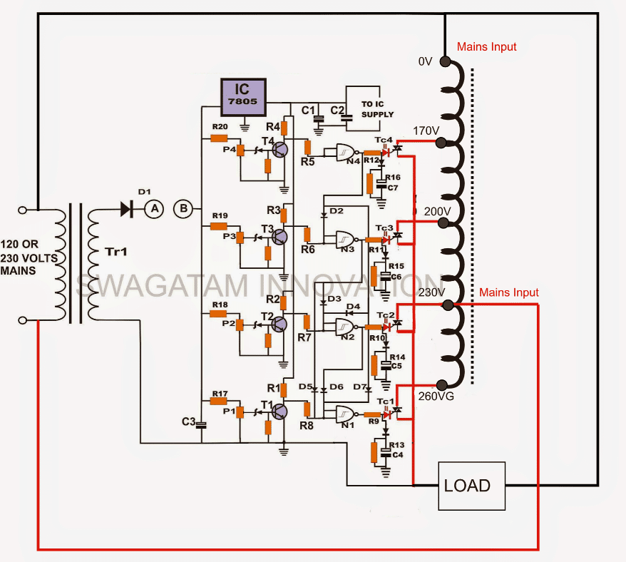
In this article I have explained a relatively simple triac controlled automatic mains voltage stabilizer circuit, which uses logic ICs and a few triacs for controlling the mains voltage levels. Why Solid State Being solid state in design, the voltage switching transitions are very smooth with minimum wear and tear, resulting in efficient voltage stabilization. […]
220V Solid State Relay (SSR) Circuit using Triac and OptoCoupler

An AC mains solid state relay or SSR is a device which is used for switching heavy AC loads at mains level, through isolated minimal DC voltage triggers, without incorporating mechanical moving contacts. In this post I have explained how to construct a simple mains operated solid state relay or an SSR circuit using a […]
Simple Triac Timer Circuit

Here’s a simple triac timer circuit which can be used for switching ON a particular device after a predetermined time, set through the given pot or the variable resistor. The shown circuit diagram of a simple triac timer can be understood by referring to the following explanation: How it Works The left hand side section […]