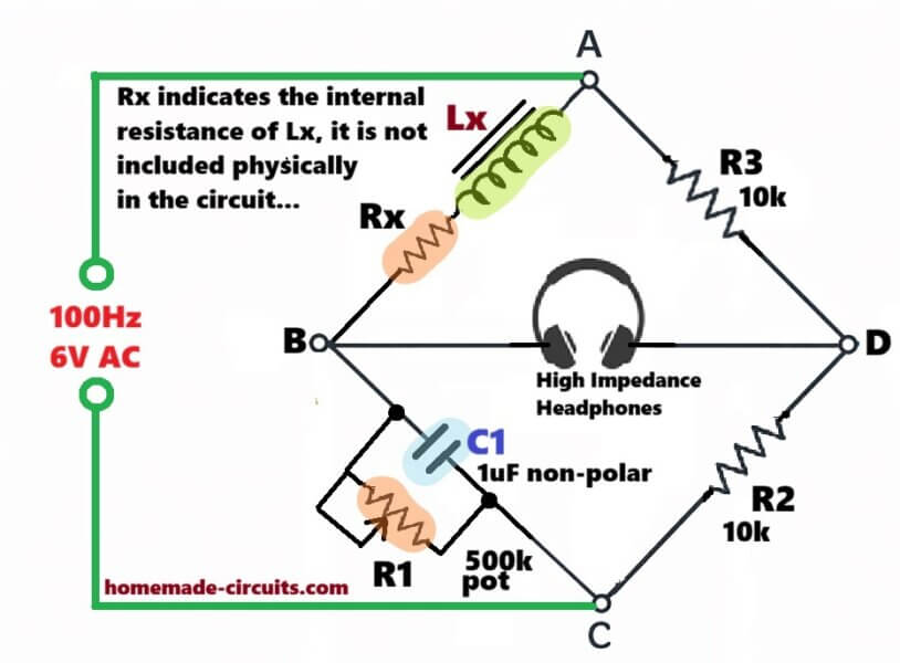
For measuring high inductance like 100H, the bridge we use is: James Clerk Maxwell Bridge which people also call Maxwell Inductance-Capacitance Bridge. It is made for medium to high Q inductors but when the inductance is large then it still behaves nicely, so people mostly prefer this one. Audio/Video Representation Basic Concept Basic idea of […]
Bridge
SG3525 Full Bridge Inverter Circuit
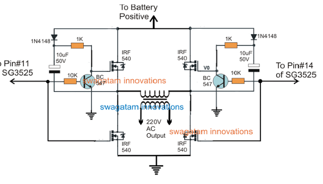
In this post we try to investigate how to design a SG3525 full bridge inverter circuit by applying an external bootstrap circuit in the design. The idea was requested by Mr. Mr. Abdul, and many other avid readers of this website. Audio/Video Representation Why Full-Bridge Inverter Circuit is not Easy Whenever we think of a […]
IC IR2111 H-Bridge Inverter Circuit with Shut Down

This circuit is basically a H bridge inverter where two IC IR2111 are working for driving four MOSFETs that are connected in H bridge way. We also see that there is a overload and over current shut down using BC547 small transistors. So what happens is that we can run a load with AC waveform […]
IR2111 H-Bridge Inverter Circuit with Soft Start

Here we see this circuit diagram which is full H-Bridge using 4 power MOSFETs and 2 IR2111 high side driver ICs. That means this circuit is for making full bridge inverter which converts DC into AC. Power Supply Part We have +600V DC at top rail, written as +600V max. And ground (0V) at bottom. […]
Simple H-Bridge Inverter Circuit using IR2184 ICs

In this post we will try to understand this full bridge or H-bridge inverter circuit using IR2184 ICs. Let us begin breaking it down section by section. If you do not want to read the full article, you can simply watch the following video instead: What This Circuit is Doing: So here basically we are […]
H-Bridge Bootstrapping
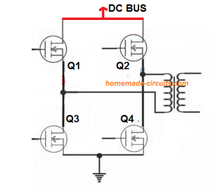
Bootstrapping is a crucial aspect that you will find in all H-bridge or full bridge networks with N-channel mosfets. It is a process in which the gate/source terminals of the high side mosfets are switched with a voltage that’s at least 10V higher than its drain voltage. Meaning, if the drain voltage is 100V, then […]