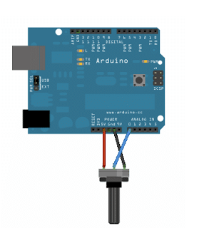
In this Arduino basics I have explained the code implementation procedure wherein an external analogue signal is fed to the Arduino analogue input and translated or converted into a correspondingly proportionate digital readout. Here we employ a variable resistance in the form of a pot as the analogue signal source. Analog Read Serial In this […]
Analogue
Simple Frequency Meter Circuits – Analogue Designs
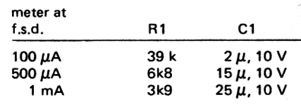
The following simple analogue frequency meter circuits can be used for measuring frequencies which may be either sine wave or square wave. The input frequency which is to be measured must be at least 25 mV RMS, for optimal detection and measurement. The design facilitates a relatively wide range of frequency measurement, right from 10 […]
Simple Analogue Weighing Scale Meter Circuit
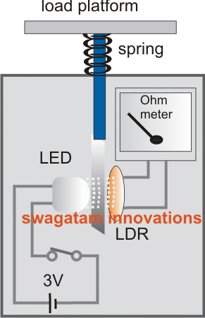
Learn a super simple procedure to make a weighing scale meter circuit useful for measuring smaller magnitudes of weight. The Concept The concept is very simple, a light beam is allowed to pass through a linearly colored ribbon and fall over an LDR. The color shade of the ribbon positioned in front of the light […]
Simple IC Tester Circuit [Test Digital and Analogue ICs]

The IC Tester is simple to use. You don’t have any switches to configure or lengthy test processes to complete. The universal IC Tester is a static tester, which means this does not dynamically test the IC’s operation. All ICs with up to 20 pins can be tested by this unit. ICs with more than […]
Automobile Engine RPM Servicing Meter Circuit (Analogue Tachometer Circuits)
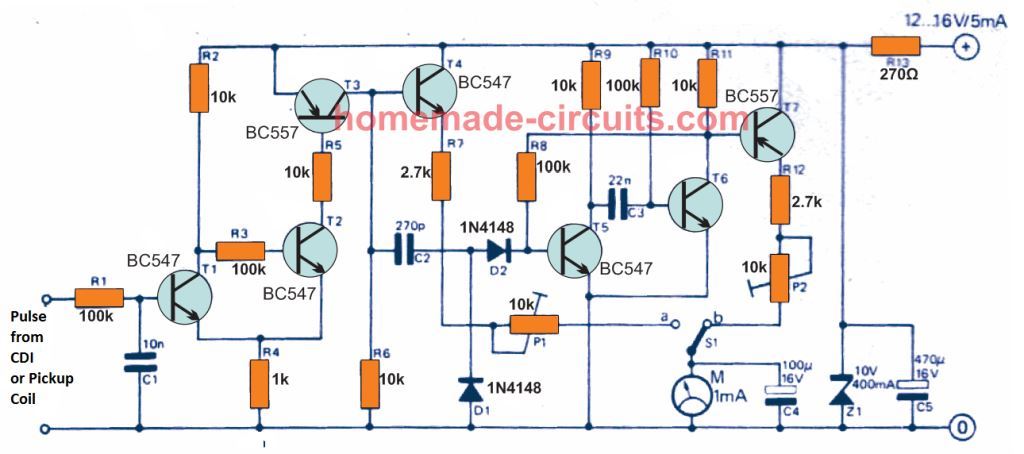
These useful lightweight, cheap, analogue tachometer circuits are developed for facilitating car or auto servicing mechanics for precisely adjusting a car ignition system RPM to get maximum efficiency from it. The proposed circuits are actually combined results of a tachometer and a dwell meter. Application The car RPM servicing meter circuit can be applied for […]
Analogue Water Flow Sensor/Meter Circuit – Check Water Flow Rate
In this post I have explained a simple water flow meter/sensor circuit using hall effect sensor and a pulse counter circuit. Referring to the diagram shown below, we can see an arrangement consisting of a circular enclosure having a couple of pipes drilled in and a circular turbine shaped wheel installed inside the enclosure. How […]