• Skip to main content
  • Skip to primary sidebar

Homemade Circuit Projects

Need circuit help? Post them in the comments! I've answered over 50,000!

Blog | Categories | About | Contact | Calculators-online
You are here: Home / Power Supply Circuits / Switching Boost Converter Circuit using IC MAX732

Switching Boost Converter Circuit using IC MAX732

Last Updated on January 8, 2024 by Swagatam Leave a Comment

The proposed boost converter circuit using MAX732 IC will allow you to have a continuous voltage of 12V with a current of 150 or 200 mA. The input voltage can be between 4.5 to 9 V, which can be produced by three 1.5V batteries, for example.

Table of Contents
  • Circuit Description
  • Construction
  • How to Use

The circuit is quite simple, we will be using a circuit from MAXIM, specifically using the IC MAX732, presented in an 8-pin DIL package.

Circuit Description

As you can see in Figure 1 below, the implementation is straightforward, and aside from the inevitable inductor and its associated Schottky diode, only a few inexpensive external capacitors are needed to achieve our goal.

MAZ 732 switching boost converter circuit

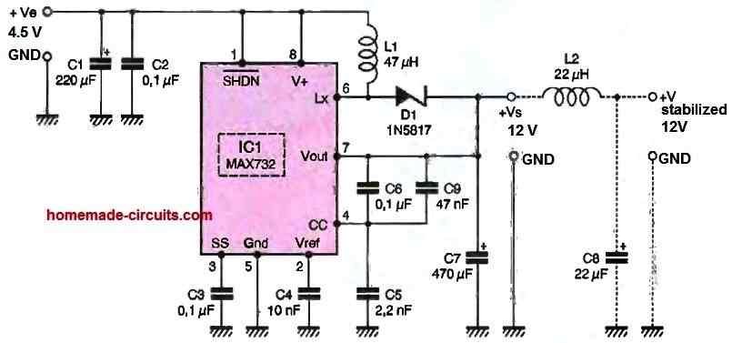
The output voltage generated by this circuit is 12 V, and if a current of 150mA is sufficient, the input voltage can vary from 4.5 to 9.3 V. However, if you need a higher current rate but do not want to exceed 200 mA, the minimum input voltage should be between 6 and 9.3 V.

As with any switching power supply, the output voltage is affected by high-frequency residues due to switching. Therefore, we have provided an optional output filter, realized using L and C, to eliminate them.

Of course, you are free to include or exclude these components, depending on the intended use of the circuit and the sensitivity of the load it powers to disturbances carried by the power line.

Construction

Once again, we have chosen only easily available components, and like for the other projects in this article, we indicate in the parts list the suppliers who have the necessary products in stock. As for the previous switched-mode power supplies, be sure to buy low ESR electrolytic capacitors when mentioned in the parts list.

The printed circuit board (PCB) designed for this project is shown in Figure 2, and the component placement diagram is shown in Figure 3, as shown below.

MAZ 732 switching boost converter PCB design

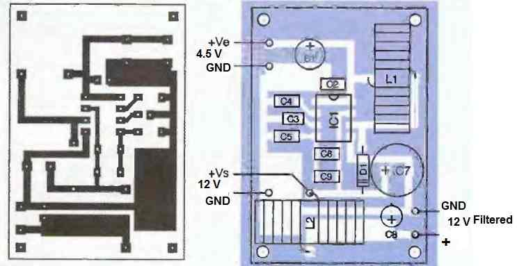
Note that the output filter is included by default, but we have also provided the option to cut this circuit above the inductor to create a version without an output filter.

The assembly presents no particular difficulties, but be sure to observe the polarity of the diode, integrated circuit, and electrolytic capacitors.

How to Use

With an input voltage within the specified range, the output voltage of 12 V should be available.

However, as with the other switched-mode power supplies, be sure to draw some current from the output if you want to measure the output voltage accurately.

This MAX732 boost circuit is protected against output shorts and input voltages that are too low. In the latter case, it locks up and does not generate any output voltage until the input voltage reaches the minimum required value for correct operation, typically 4V.

You'll also like:

  • 1.  Simple Buck Converter Circuits using Transistors
  • 2.  Higher Variable Output Voltage from IC 7812
  • 3.  How to Make a Bridge Rectifier
  • 4.  220V SMPS Cell Phone Charger Circuit
  • 5.  Transformerless Power Supply Circuit using MJE13005
  • 6.  LM324 Variable Power Supply Circuit

About Swagatam

I am an electronics engineer with over 15 years of hands-on experience. I am passionate about inventing, designing electronic circuits and PCBs, and helping hobbyists bring their projects to life. That is why I founded homemade-circuits.com, a website where I share innovative circuit ideas and tutorials. Have a circuit related question? Leave a comment.... I guarantee a reply!

Previous Post: « Simple LED Forward Voltage Drop Tester Circuit
Next Post: High Current Adjustable Switching Power Supply Circuit using L296 IC »

Reader Interactions

Need Help? Please Leave a Comment! We value your input—Kindly keep it relevant to the above topic! Cancel reply

Your email address will not be published. Required fields are marked *

Primary Sidebar

Subscribe to New Circuit Ideas

Categories

  • Arduino Projects (87)
  • Audio and Amplifier Projects (132)
  • Automation Projects (17)
  • Automobile Electronics (101)
  • Battery Charger Circuits (83)
  • Datasheets and Components (104)
  • Electronics Theory (143)
  • Free Energy (37)
  • Games and Sports Projects (11)
  • Grid and 3-Phase (19)
  • Health related Projects (25)
  • Home Electrical Circuits (12)
  • Indicator Circuits (14)
  • Inverter Circuits (87)
  • Lamps and Lights (142)
  • Meters and Testers (69)
  • Mini Projects (46)
  • Motor Controller (64)
  • Oscillator Circuits (27)
  • Pets and Pests (15)
  • Power Supply Circuits (108)
  • Remote Control Circuits (50)
  • Security and Alarm (64)
  • Sensors and Detectors (101)
  • Solar Controller Circuits (59)
  • Temperature Controllers (42)
  • Timer and Delay Relay (49)
  • Transmitter Circuits (29)
  • Voltage Control and Protection (37)
  • Water Controller (36)

Calculators

  • Battery Back up Time Calculator
  • Capacitance Reactance Calculator
  • IC 555 Astable Calculator
  • IC 555 Monostable Calculator
  • Inductance Calculator
  • LC Resonance Calculator
  • LM317, LM338, LM396 Calculator
  • Ohm’s Law Calculator
  • Phase Angle Phase Shift Calculator
  • Power Factor (PF) Calculator
  • Reactance Calculator
  • Transistor Astable Calculator
  • Transistor base Resistor Calculator
  • Voltage Divider Calculator
  • Wire Current Calculator
  • Zener Diode Calculator
  • Filter Capacitor Calculator
  • Buck Converter Calculator
  • Boost Converter Calculator
  • Solar Panel, Inverter, Battery Calculator
  • Wire Current Calculator
  • SMPS Transformer Calculator
  • IC SG3525, SG3524 Calculator
  • Inverter LC Filter Calculator

People Also Search

555 Circuits | 741 Circuits | LM324 Circuits | LM338 Circuits | 4017 Circuits | Ultrasonic Projects | SMPS Projects | Christmas Projects | MOSFETs | Radio Circuits | Laser Circuits | PIR Projects |

Recent Comments

  • Swagatam on Understanding SG3525 IC Pinouts
  • Dan on Understanding SG3525 IC Pinouts
  • Swagatam on High Current Wireless Battery Charger Circuit
  • Swagatam on Timer Based Cell Phone Charger Circuit
  • Nitesh Agrawal on Timer Based Cell Phone Charger Circuit

Company

  • Privacy Policy
  • Cookie Policy
  • About Me
  • Contact
  • Disclaimer
  • Copyright
  • Videos
  • Sitemap

Social Profiles

  • Twitter
  • YouTube
  • Instagram
  • Pinterest
  • My Facebook-Page
  • Quora
  • Stack Exchange
  • Linkedin
  • © 2025 · Swagatam Innovations