A very simple yet highly sophisticated modified sine wave inverter circuit is presented in the following post. The use of the PWM IC TL494 not only makes the design extremely economical with its parts count but also highly efficient and accurate.
Audio/Video Representation
Using TL494 for the Design
The IC TL494 is a specialized PWM IC and is designed ideally to suit all types of circuits which require precise PWM based outputs.
The chip has all the required features in-built for generating accurate PWMs which become customizable as per the users application specs.
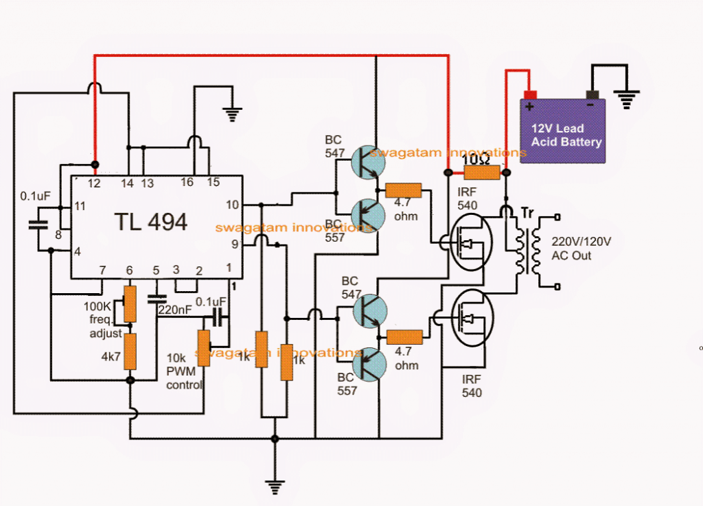
Here I have explained a versatile PWM based modified sine wave inverter circuit which incorporates the IC TL494 for the required advanced PWM processing.
Referring to the figure above, the various pinout functions of the IC for implementing the PWM inverter operations may be understood with the following points:
Pinout Function of the IC TL494
Pin#10 and pin#9 are the two outputs of the IC which are arranged to work in tandem or in a totem pole configuration, meaning both the pinouts will never become positive together rather will oscillate alternately from positive to zero voltage, that is when pin#10 is positive, pin#9 will read zero volts and vice versa.
The IC is enabled to produce the above totem pole output by linking pin#13 with pin#14 which is the reference voltage output pin of the IC set at +5V.
Thus as long as pin#13 is rigged with this +5V reference it allows the IC to produce alternately switching outputs, however if pin#13 is grounded the outputs of the IC is forced to switch in a parallel mode (single ended mode), meaning both the outputs pin10/9 will begin switching together and not alternately.
Pin12 of the IC is the supply pin of the IC which can be seen connected to the battery via a dropping 10 ohm resistors which filters out any possible spike or a switch ON surge for the IC.
Pin#7 is the main ground of the IC while pin#4 and pin#16 are grounded for some specified purposes.
Pin#4 is the DTC or the dead time control pinout of the IC which determines the dead time or the gap between the switch ON periods of the two outputs of the IC.
By default it must be connected to ground so that the IC generates a minimum period for the "dead time", however for achieving higher dead time periods, this pinout can be supplied with an external varying voltage from 0 to 3.3V which allows a linearly controllable dead time from 0 to 100%.
Pin#5 and pin#6 are the frequency pinouts of the IC which must be connected with an external Rt, Ct (resistor, capacitor) network for setting up the required frequency across the output pinouts of the IC.
Either of the two can be altered for adjusting the required frequency, in the proposed PWM modified inverter circuit we employ a variable resistor for enabling the same. It may be adjusted for achieving a 50Hz or 60Hz frequency on pins9/10 of the IC as per the requirements, by the user.
The IC TL 494 features a twin opamp network internally set as error amplifiers, which are positioned to correct and dimension the output switching duty cycles or the PWMs as per the application specs, such that the output produces accurate PWMs and ensures a perfect RMS customization for the output stage.
Error Amplifier Function
The inputs of the error amplifiers are configured across pin15 and pin16 for one of the error amps and pin1 and pin2 for the second error amplifier.
Normally only one error amplifier is used for the featured automatic PWM setting, and the other error amp is kept dormant.
As can be seen in the diagram, the error amp with the inputs at pin15 and pin16 is rendered inactive by grounding the non-inverting pin16 and by connecting the inverting pin15 to +5V with pin14.
So internally the error amp associated with the above pins remain inactive.
However, the error amp having the pin1 and pin2 as the inputs are effectively used here for the PWM correction implementation.
The figure shows that pin1 which is the non-inverting input of the error amp is connected to the 5V reference pin#14, via an adjustable potential divider using a pot.
The inverting input is connected with pin3 (feedback pin) of the IC which is actually the output of the error amps, and enables a feedback loop to form for pin1 of the IC.
The above pin1/2/3 configuration allows the output PWMs to be set accurately by adjusting the pin#1 pot.
This concludes the main pinout implementation n guide for the discussed modified sine wave inverter using the IC TL494.
Output Power Stage of the Inverter
Now for the output power stage we can visualize a couple of mosfets being used, driven by a buffer BJT push pull stage.
The BJT stage ensures ideal switching platform for the mosfets by providing the mosfets with minimum stray inductance issues and quick discharge of the internal capacitance of the fets. The series gate resistors prevent any transients trying to make its way into the fet thus ensuring the operations to be entirely safe and efficient.
The mosfet drains are connected with a power transformer which could be an ordinary iron cored transformer having a primary configuration of 9-0-9V if the inverter battery is rated at 12V, and the secondary could be 220V or 120V as per the user's country specs.
The power of the inverter is basically determined by the transformer wattage and the battery AH capacity, one can alter these parameters as per individual choice.
Using Ferrite Transformer
For making a compact PWM sine wave inverter, the iron core transformer can be replaced with a ferrite core transformer. The winding details for the same may be seen below:
By using super enamelled copper wire:
Primary: Wind 5 x 5 turns center tap, using 4 mm (two 2 mm strands wound in parallel)
Secondary: Wind 200 to 300 turns of 0.5 mm
Core: any suitable EE core which would be capable of accommodating these winding comfortably.
Automatic PWM Voltage Regulation
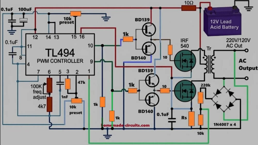
The above diagram shows how the manual PWM control action could be upgraded into a full automatic output PWM control with respect to the output voltage changes.
When heavy load comes on the output side then output voltage may start dropping a bit, so now the feedback voltage at pin 1 also drops together since both are linked.
TL494 reacts almost immediately to that condition and increases the PWM duty cycle automatically.
Because of that, MOSFET stays ON for longer time, transformer transfers more power, and output voltage starts climbing back toward normal again.
In the same way, if output voltage goes too high somehow then feedback voltage also rises, so now TL494 reduces the PWM duty cycle by itself.
That pulls the output voltage back down again near the proper level.
This whole thing keeps happening continuously in the background, therefore output voltage stays regulated automatically even when load conditions keep changing around.
TL494 Full Bridge Inverter Circuit
The following design can be used for making full bridge or H-bridge inverter circuit with IC TL 494.
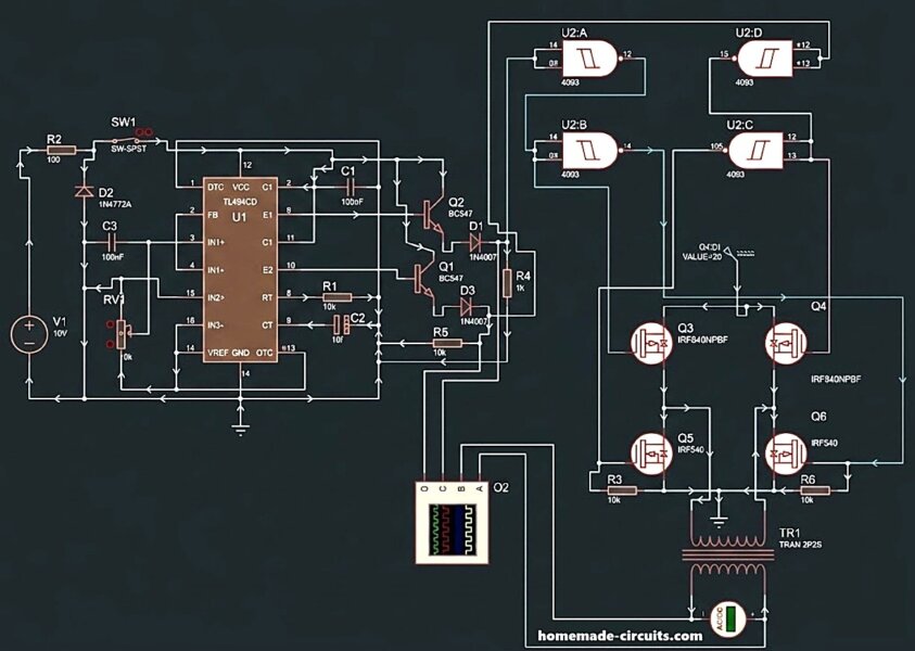
As can be seen, a combination of p channel and n channel mosfets are used for creating the full bridge network, which makes things rather simple and avoids the complex bootstrap capacitor network, which normally become necessary for full bridge inverters having only n channel mosfet.
However incorporating p channel mosfets on the high side and n channel at the low side makes the design prone to shoot-through issue.
To avoid shoot-through a sufficient dead time must be ensured with the IC TL 494, and thus prevent any possibility of this situation.
The IC 4093 gates are use for guaranteeing perfect isolation of the two sides of the full bridge conduction, and correct switching of the transformer primary.
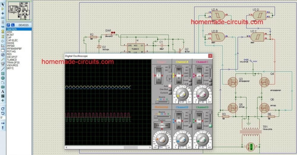
Simulation Results
TL494 Inverter with Feedback
A very simple yet accurate and stable inverter circuit using IC TL494 is shown in the below diagram.
The inverter includes a feedback control system for automatic output voltage correction, applied at the error amplifier pin#1 of the IC.
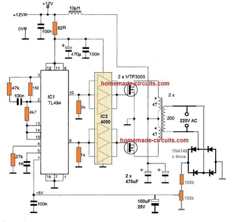
The 100k preset can be adjusted appropriately for setting up the required constant output voltage limit.
The transformer shown is a ferrite core transformer, and therefore the frequency is set at a very high level from the IC. Nevertheless, you can easily use an iron core based transformer and reduce the frequency to 50 Hz or 60 Hz for 120 V output.


Questions & Answers
Thanks so much Mr Swagatam. Please what frequency will this Ct/Rt you used in the circuit give? 50Hz or 60Hz?
thanks II
you can adjust the frequency to any desired levels by using the 22k preset and by confirming it with a DMM across the output pins of the IC.
Thanks. Also at what value must the 10k PWM Control(10k variable resistor) be set to ensure efficient performance
you will need to check the output voltage from the transformer and simultaneously adjust 10k preset until the voltage is adjusted to the nearest normal level.
Hi swagatam majumdar,
is possibible to use this circuit for get an output high voltage DC (about 310vdc), doing swing the tl494 to high frequency and using an ferrite core transformer?
thank you
Hi franco, yes surely the design can be used for generating high voltages to any desired levels.
the transformer will have to be designed as per the 310V spec for enabling the production of this voltage.
I have another question. Can i use an atx transformer connected in reverse way?
thank you
if it has 5 + 5 turns in the primary, and assuming the battery is 12V then it would possibly work.
Hi sir, thanks for work done but am just requesting you to design for an INVERTER circuit diagram using IC SG3524 where the output voltage will be proportional to the input voltage.
Meaning if the output will be constant on a certain range of LOAD regardless of the dropdown of the input voltage upto a certain level. Thanks
Hi Kakooza, I already have this design in my website, you can see it here:
https://www.homemade-circuits.com/2013/01/modified-sine-wave-inverter-circuit.html
Thanks. Please how do I make use of this design to ensure automatic output voltage regulation and low battery cut-off protection feature?
once you set the output voltage to the required level by adjusting the PWM preset, the circuit will remember it and try to keep it constant
low battery cut is not included in this design, you may use the opamp circuit that's shown in the following design and apply the same for this circuit
use the second circuit from the following article:
https://www.homemade-circuits.com/2011/12/how-to-make-simple-low-battery-voltage.html
Hi swataman majumdar,
can i build the circuit before on breadboard or this is a problem?
i wanted to swing the IC to high frequency and so i think to replace the resistor 22k + 4,7k with an fixed resistor 3,3k and the capacitor of 1 nf with another of 4700pf.
in this way the IC have a frequenzy (sawtooth) of 70khz about.
How can i do for building an toroidal transformer that work with 70 khz about?
the idea is to have an high voltage in output using a smaller toroidal transformer.
Thank you so much for your time.
kyu9971
Hi franco, yes you can make the trial version on a breadboard, no issues.
initially you can try around 40 turns of 1mm wire on your torroidal transformer, you can reduce or increase number the turns proportionately further, in order to achieve the intended high voltage level
Hi swagatam,
excuse me for all these questions, but 40 turns you mean of primary winding with central tap 20 turn + 20 turn?
For secondary winding?
Thanks
franco
Hi Franco, yes it should be 20+20 for the primary with a 12V supply, the secondary can be upto 1000 turns or even more, as per the required high voltage needs.The thickness of the wire can be about 0.2mm to 0.3mm
Begin with 1000V and check the output level, then you can increase the no of turns proportionately to any degree until the required level is achieved
To get 50 Hz frequency, what will be the values of Capacitor and Resistor?
you will need to adjust the 22k pot and check the frequency at the output pins until 50Hz is achieved
Mr Swagatam, please can I use IRL3713PBF OR IRLS3036 power MOSFET for inverters?
Hello ii,
you can use any mosfet with the above circuit, just make sure it's V and I matches with your load specs.
hello……..mr Swagatam
had made circuit as above ,it run well when i give pulse but when m remove pulse circuit MOSFET(IRFZ44N) start to heat
it aslo work well in H bridge conf,
please solve my query please….
hello janak,
the IC already has an internal oscillator, no external pulse is required here.
and yes without a frequency the fets will stall and instantly burn, a frequency is the only way to keep the inverter and the fets running….
Sir does this mean the inverter does not need feedback from the output of the inverter.?
Does it mean that if it is a 1500w or 5000w inverter rated at 220v operating at full load it will regulate it self to steady 220v who operating at full load?
Mr Alex, that's correct, because the PWM is set by referring to a constant 5V generated at pin14 of the IC, once set, the PWMs will not change regardless of the output load, unless the load spec is too high and the reference 5V is disturbed due to a alarming drop in the battery voltage
So basically sir what this means is that
1)the 10k pot can be used to adjust the output voltage.
2)even the modified sine wave inverters that employs the SG3524/SG3525 chip or even ur own SG3525 modified sine wave circuit you posted on your site earlier can eliminate the feedback transformer from the output inverter itself and all that rectification and all that will be eliminated and we can rig the SG3525 to work without all those diode rectication and the small feedback trafo,exactly in the same way the TL494 works in maintaining constant voltage under varying load conditions.?
By the way it's Michael not Alex.
That's right Michael.
Because, according to me as long as the 5.1V reference stays constant the PWM would also stay constant which in turn would make sure that the outputs voltage stays constant.
so yes even for SG3524/3525, the principle of operation looks alike and therefore an external feedback may not be required for the corrections.
sorry for the confusion, your questions are much identical to what Mr. Alex (another dedicated member) normally asks,,,that's why I mistakenly thought you to be him.
Hello Mr. swagatam I want to do this one again I have bought all the requirements now but I want to know how many volt and ahms transformer should I use to get 300watt or 500watt? Thank you sir.
If your battery is 12V then the trafo will need to be 500/12 = 41 amps ans 9-0-9V
battery will to be at least 100 AH
Hi sir Swagatam, I want to ask one question; Sir, to 50hz what fixed resistor (RT) is needed instead of 22k pot.
Hi clickbirth, I have not yet researched this parameter so I have not idea about the formula for this, alternatively you can test it by adjusting the 22k pot and then verify the resistance value across the pot for determining the value
Hi Mr. swagattam can i use IRF 3205 instead of the mosfet above and a Microwave Oven Transformer with its secondary removed and rewired using 10 gauge wire centre tap?
Mr. mach3z, yes you can use the mentioned mosfet.
the entire trafo prim+sec+size will need to be appropriately dimensioned for the specified load
sir we design the above circuit but its not work. Actually I can't understand the working of the circuit. I have many troubleshooting problem. Kindly mention the working of the circuit..
Thank you
what frequency are you getting at the pin9 and pin10??
…I have already explained everything comprehensively in the article, if you have any specific questions, you can put them here.
very impressive circuit, its working on high freq. 16khz and low freq. 60hz. the only problem here is the pwm control, yes we can adjust the voltages in fix value. but when the source voltage up let say 12v to 15v the output voltages also increases. unlike my current pwm squarewave sg3524 has a perfect voltage control even we use 12v-24v supply the output voltage remain steady. sorry for my bad english, i will appreciate if our master fix or correct the pwm section thank you. God Bless!
OK thank you very much, in that case I'll request you to check the two designs and find out the what may be causing the two designs to work in slightly different ways, because I have configured he pinouts as per the datasheet of the IC and exactly as per the pinout functions of the IC.
By the way the above circuit does not include an output voltage correction circuit stage…that's an external ad-on circuit which may be required for controlling the output voltage, and may be that is why the above circuit is not controlling the output voltage.
my bad i though this design got output voltage controller. sorry for my comment earlier, pls help us to attach the voltage controller on pin 1. theres another question i would like you to know, why when we use the push pull transistor the transformer generate to much noise, yeah the gate voltage become high if we use push pull transistor but the waveform on oscilloscope become too small? my testing design none transistor.
you can refer to the following article and use it for the required application:
https://www.homemade-circuits.com/2014/01/automatic-output-voltage-regulator.html
remove the transistor collector diodes, and connect the collector directly with pin1
Hi Swagatam,
I'm testing this circuit on breadboard. I'm using the same values as you have mentioned. I'm using a 12-0-12 10A transformer. When I check the output voltage, it's in the range of 300v. Adjusting PWM control has no effect in the output voltage. The output frequency is about 35KHz (checked after stepping down). When I adjust the frequency pot, it reduces a little. but not much. Shouldn't the frequency read in the range of 40 – 80Hz? Why it reads 35KHz?
When I look at the datasheet, I see that this is the formula for Frequency.
Single-ended applications:
f = 1/Rt*Ct
Push-Pull applications
f = 1/2Rt*Ct
I believe this is a push pull application and if we use the second formula with the values you have given:
1/2*15000*.000000001 = 33333Hz.
This is the frequency I measure after stepping down the output.
But if I make these changes according to the formula:
F = 1/2*45000*.00000022 ~ 50Hz. (100K VR set to ~45K and a 220nf). With these changes, I get correct 50Hz. Now my multimeter measures 250v but I'm still not able to adjust the voltage using the PWM pot. Should I add a feedback from the output?
please let me know if what I'm doing is correct.
Thanks,
Vijay
Hi Vijay,
the PWM pot is referenced to ground, please check whether you have connected the ground with the PWM pot or not, otherwise it will not work.
after connecting make sure the pin#1 voltage changes when this preset is adjusted….this is supposed to change the reference voltage for the error amp which in turn is supposed to narrow or widen the PWMs
or simply short the pin#1 with ground and see the response.
I'll the frequency components values in the diagram soon.
Hello Vijay, have you done the adjustment as posted by Swagatam? Please let's know the result.
Hello Sir!
Can I use a 48 Volt battery system here?
And is it a way to use a transformer without CT?
(hard to come by, that will fit the 48V, 20-0-20?)
Using one P-ch, one N-ch MOSFET. Maybe in pair's like in this:
https://www.homemade-circuits.com/2012/05/make-this-1kva-1000-watts-pure-sine.html
I find a lot of interesting things here,
Thank You.
Thanks baron,
yes you can use the design for 48V operation, just make sure the IC section is operated with a 12V stabilized supply, which can be easily implemented using an emitter follower transistor stage….you may refer to the following article and see how the BC546 is configured for the same.
https://www.homemade-circuits.com/2014/11/48-v-inverter-circuit.html
for eliminating the CT, you can incorporate the following design:
https://www.homemade-circuits.com/2014/01/simplest-full-bridge-inverter-circuit.html
the load is your trafo primary….and the AC rectified line may be replaced with 48V or the desired battery voltage.
Hi,
Great web site and you must be very busy with all these circuits.
I have what maybe a dumb question, when you say "primary configuration of
9-0-9V" for the sine wave PWM inverter, do you mean 9 turns to center tap?
I see you have 9V there, does that mean 9Volts? Or a transformer which would
be 9V if you were to connect 220vac to the secondary as if it were the primary
in a step down application?
Thanks!
Marc
Hi, thanks
It means that the primary should be rated at 9V-0-9V with reference to the 220V secondary.
yes that's right if 220V was supplied at the 220V side that's supposed to generate a 9V-0-9V across the other side.
i made this inverter exactly the way you designed it and it worked. I used it to power 100w bulb. I used a ferrite transformer i found in my damaged Chinese 12v 1000w compact inverter, though it was labelled 1000w but I doubt. Now, I want you to help me increase it to 36v 2000w. I know that the IC will be fed with 12v, I will use 7812 and 7824 regulators ic to regulate 36v to 12v for the circuit. What will be the turns of the ferrite transformer for 2000w? if i want to use a high frequency, i know that i have to select rt/ct network to obtain the high frequency. i want to know the frequency suitable for a 36v 2000w compact inverter using a ferrite transformer? Thanks
you can try by the rule of thumb and use 15 + 15 turns for the primary, and 330 turns at the secondary.
primary wire could be 2 mm thick, and the secondary 0.5mm
frequency could be anywhere around 20 to 50kHz, check by trial and error which gives the optimal response….use EE core for the transformer
Hi Mr.Swagatam
Thanks for your sharings. is it possible to modify this circuit for 14.8v dc input to 220v/ 110v ac output?
Thanks
Hi AD,
the above circuit is designed to work with a 14V supply, the output will depend on the winding rating of the trafo…could be 220V or 110V