Here's a simple triac timer circuit which can be used for switching ON a particular device after a predetermined time, set through the given pot or the variable resistor.
The shown circuit diagram of a simple triac timer can be understood by referring to the following explanation:
How it Works
The left hand side section comprising the IC 4060 becomes the basic delay generator stage. As we all know, the IC 4060 is an extremely versatile time delay generator chip which has a built in oscillator for the required fundamental timing clocks.
The components connected at the pin#9,10 and 11 form the time delay determining parts of the IC.
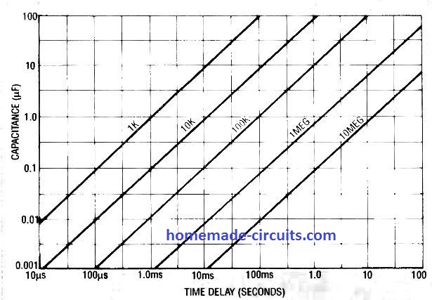
Precisely, the resistor at pin#10 and the capacitor at pin#9 are responsible for fixing the delay period and may be adjusted for acquiring the required predetermined switching output.
This IC has 10 discrete outputs which produce delays or oscillation periods which are twice to the previous pinout in the order.
Here pin#3 produces the largest delay, followed by pin#2 and then pin#1 and so on as per the specified pinout order. So suppose pin#3 produces delay interval of 1 minute, then pin#2 would produce the same at an interval of 30 seconds, pin#1 at 15 seconds and so on.
Since pin#3 is specified with the highest time interval, we use this pinout as the output.
Therefore suppose we set the RC at pin#9 and 10 with a maximum delay of 2 hours, pin#3 would be assigned to generate alternately changing ON/OFF pulses, having equal delay intervals of 2 hours, meaning initially the output would be OFF for 2 hours, then ON for next 2 hours and so on as long as its powered.
The above explains the IC 4060 configuration, now I have explained about the triac configuration.
As we can see, the output pin#3 is directly connected to the gate of the triac, while the triac A1 and A2 are terminated with the load and the other specified parameters.
When power is first switched ON, C3 at pin#12 of the IC4060 makes sure that the timing count initiates right from zero by resetting pin#12 with a short pulse.
The output pin#3 now initiates with a logic zero output while the IC internal timer starts counting.
Due to the logic zero, the triac stays switched OFF initially along with the load.
Once the predetermined delay interval lapses, pin#3 instantly becomes high, triggering the triac and the load.
The diode connected across pin#3 and pin#11 plays an important function of latching the IC counting process.
If this diode is removed, the counting process will continue and after 2 hours the triac will be again become switched OFF, and this procedure will go on repeating every after 2 hours.
The diode shuts off this operation, and lathes the IC to the ON position permanently.
The above situation provides us with another interesting application of the proposed circuit, by removing the diode we can convert the above circuit into an AC lamp flasher circuit, the flashing rate being set by the RC components.
Also note that irrespective of the RC parts you have the option of selecting/connecting the remaining outputs of the IC with the triac gate for getting a diverse range of time delays.
Circuit Diagram for Delay ON Timer
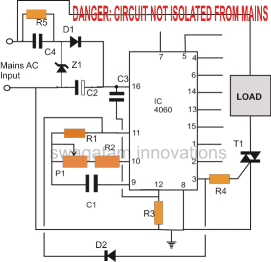
The above triac controlled timer circuit becomes suitable for applications which requires a delay switch ON.
For applications which require a delay switch OFF meaning in cases where a load needs to be switched off after a predetermined time interval, the above circuit can be modified as given below:
Circuit Diagram for Delay OFF Timer
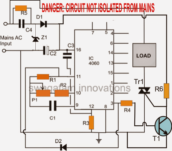
PCB Layout
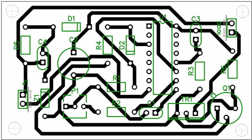
Parts list for the above simple triac timer circuit
- R1 = 2M2
- R3 = 100K
- R2, R4, R6 = 1K
- R5 = 1M
- C1 = 1uF/25V (must be non-polar, use more in parallel for higher delays)
- C3 = 0.1uF disc
- C2 = 100uF/25V
- C4 = 0.33uF/400V
- Z1 = 15V 1watt zener
- Tr1 = BT136
- T1 = BC547
- D1, D2 = 1N4007
- P1 = 1M pot
Using a Transformer DC Supply
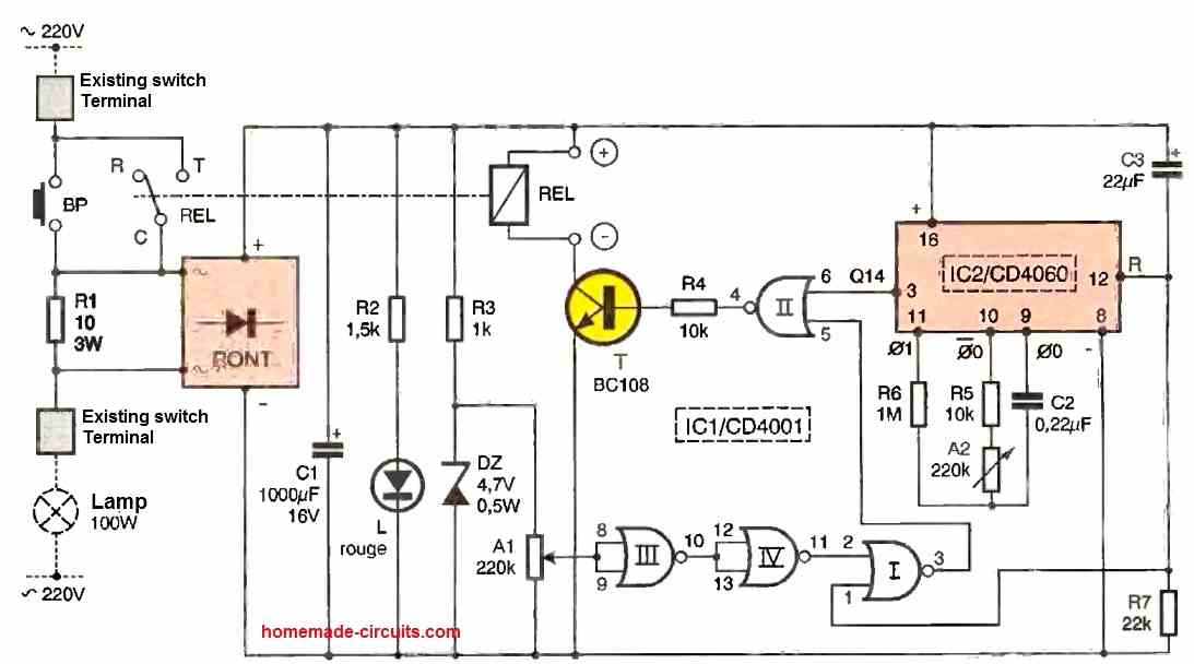
The above simple timer circuit can be also built using a transformer DC supply, as shown below:
All diodes are 1N4007, and the relay is 12V/400 ohm, 10 amp
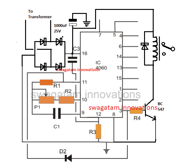



Questions & Answers
Hallo Mr. Swagatam
I have build a dark sensor to switch on the CFL lamp 220 volt. I just build one with a simple SCR sensor. But if the LDR is getting dark or getting bright, the CFL got flicked for several time. so I have an idea to make a delayed switch on. So if LDR getting dark the lamp is not ON immediately, but the lamp is ON for several minutes after ldr getting dark and vice versa if LDR getting bright.
would you have a suggestion about it ?
THANKS
Hi mbah,
your circuit cannot be upgraded, for getting improved results you may have to utilize better designs as shown here:
easy-electronic-circuits.blogspot.in/2013/07/simple-light-activated-switch-using.html
thanks for ur suggestion Mr. Swagatam…
Using ne555 is my next plan for applying this feature. But I doubt :
1. can the IC ne555 be supplied with transformatorless power suply ?
2. can the IC ne555 drive the SCR gate for subtituting mechanical relay ?
3. can I replace the capasitor c1 with larger to make a delayed switching…?
so I want to try to make it…
thank a lot
Hi Mbah,
Yes all the points you have are possible with the shown circuit
thankyou
Yes it will work with a DC adapter also.
you can use a standard transistor/relay driver stage in place of the triac.
the voltage should be a fixed type around 12V or at the selected relay voltage, if it's fluctuating too widely then I am afraid the relay will not respond at the lower voltages, using a converter will make the circuit very complicated.
you will have to adjust the RC components for setting the preferred time interval.
Time delay will not be affected at supply voltages between 5V and 15V.
Hello Miguel,
you can use the above circuit,just replace the triac with a transistor/relay stage.
You can power it with a 12v ac/dc adapter instead of the transfomerless power supply.
did you understand the function of the zener here?
everything is perfect in the circuit, nothing needs to be changed
During negative cycles C4 would get discharged through R5 and the cycle would continue, I would like to check it practically and then I'll put my comment back here.
Putting the zener immediately after C4 is not a bad idea but in the above condition also the circuit should work..let me check it.
The HV capacitor needs a clean discharge path so I'll stick to your suggestion. Thanks for that!
Thanks very much! I appreciate your valuable input.
sir can this carry load of 3000watt to 5000watt
may be, if a 40 amp triac is used
which number of triac is 40amps to 100amps
BTA41/600
sir can i use half rectifier circuit to charge 200amp battery
yes you can do it.
Sir I need a circuit in which i can operate a 12 volt dc relay . On switching the relay should remain ON for 5 seconds and after 5 seconds the relay should go OFF for 5 seconds and after 5 seconds it should turn on for for 5 seconds again.his cycle should continue untill supply to the circuit is disconnected.
you can try the 4060 timer circuit that's given in the above article, replace the triac with a transistor/relay driver stage and adjust the pot for getting the desired timing
use a 12V adapter to power the circuit.
Thank you sir . That's one I was really looking for. I made it successfully and working well. Can any thing be connected to this circuit to protect it? Kindly let me know what are the main point which we should note down from a transistor data sheet regarding any transisor. Thank you.
Hi Mujahid,
In transistor datasheet you should only look for the maximum breakdown voltage that it can handle across its collector/emitter and also the breakdown current across these terminals
Sir I would like to know a few questions
can we use all or some of the outputs of the above explained ic at the same time?
Can a relay be directly connected to an ic without any transisor. Thanks a lot
Yes you can use any desired number of outputs simultaneously, but they should never be interconnected directly.
Relay cannot be used directly with CMOS devices since their output have very low current, not specified for driving loads like relay etc.
A circuit needs 12 volt and 20mA. Will this effect the circuit if it is connected to a 12 volt 200Amp battery? What happens if the required volt remains the same and amperes are increased to the circuit?
12v 200AH batery cannot be charged with a 20ma supply.
Sir kindly let me know why this zener diode has been used in the above circuit?
In a few circuit whenever tried to connect zener diode it gets hot why does it happen so?
zener is used so that C4 can operate correctly….with a 0.33uF for C4 here, the zener will not become hot.
Actually I mean to know can I operate a circuit of 12v 20mA with a 12v 200Ah battery ? I don.t want to charge the battery.
yes you can operate a 12v 20ma circuit with a 12v 200ah battery
Sir I want to know a very important point is it possible to power the above circuit with both mains and a battery as well in a way in which the battery should not charged with the mains supply.actually I need to power the circuit when mains is unavailable.the battery should remain safe from charging.thank you
Do you need a timer circuit or just a mains changeover relay for switching the battery ON/OFF?
If your need is a timer circuit then you can use the above circuit with both mains and battery also.
Preferably use a 12V DC adapter for mains operation of the circuit instead of the capacitive power supply.
Let me explain my question in a better way.I need a timer circuit only not any changeover I want to operate the above circuit with both mains(using an adaptor)and a battery simultaneously. My purpose of using two different supplies simultaneously is to operate the circuit even when the mains is unavailable. In case of the unavailability of mains the battery will operate the circuit but the problem is to keep the battery safe from charging of mains supply. Can I use a diode in battery supply?
OK, yes you can operate the timer circuit through mains and 12V battery as well, for preventing the battery from receiving the 12V DC from the adapter you can use a blocking diode as correctly suggested by you.
With the above circuit is it possible that its On Off cycle repeats only 3 times, after 3 times its ON OFF cycle should stop permanently.
it can set in multiples of 2, like 2 times ON/OFF, 4 times ON/OFF, but not 3 times or 5 times etc.
"The higher the capacitance the higher voltage drops."Sir is my understanding about voltage dropper capacitor( capacitor used in place of a transformer to drop voltage) is correct or not?
no i's incorrect, first of all it's not voltage but current that's dropped, higher capacitance means higher current and vice versa.
That.s very kind of you. Actually sir I don.t know much about electronics but this is your help that I.'ve made a mobile operated relay circuit that.s a bit different from yours. And there.s one to operate the generator automatic start and shut down. That.s all great. I read your blogs regularly. Sir I!ve difficulty in understanding the terminology of electronics.would you help me.
You can ask questions whenever you have doubts about any particular circuit, I'll answer those, and gradually you will learn the different aspects of the subject.
sir i have made the above circuit it working well but i want to drive a 12 volt relay what transistor should i use to drive it
you can use a BC547 transistor
Sir if i use the above circuit as flasher using the Triac bt136 how much load it can carry.thank you.
300 watts
A mobile set under continuous charging as you have configured one in the cell phone operated bell circuit will be ok? I mean overcharging won't damage the cell phone?
every cell phone has an inbuilt over charge shut off feature, so it's safe.
Dear sir my question is regarding one of your explained circuit that is proximity circuit. If an IR led and BP104 and a npn transistor and a relay is configured in such a way when the beam of IR led is reflected and falls on photo diode and it triggers the transistor and the transistor gets saturated thus operating the relay for the time as long as the reflected beam falls on photo diode. I mean to know that with these few components it possible to make a simple proximity circuit. Thank you.
Yes it's possible.
Yes it's possible.
A photo diode or a photo transistor is triggered by infrared light only or they can be triggered by any light like sun light or any other bulb. Please explain about photo transistor and photo diode. Thank you
it can be triggered by any light source that's why we use a pulsed light while using it as a detector in a circuit, the receiver responds only when the PD receives the pulsed signal from the specified transmitter and other light sources are ignored
Sir can you help me in making a proximity circuit for water tape I need a simple circuit. I tried to make it with the help of infrared receiver found in a computer mouse but it.s not responding well as I need it.
In the proximity circuit the photo diode BP104 is specifically for infrared light source or this one is same as other photo diode?i
Mujahid you can modify the following circuit as per your application requirement:
https://www.homemade-circuits.com/2013/03/simple-reliable-infrared-ir-remote.html
Sir if i want to stop the ic after specific number of ON and OFF cycle then what i should do? I need only 3 cycles. I have made this circuit when three cycles complete I cut this circuit with a timer circuit via a relay. Now I don.t want to use the relay.tell me an easy way to use the above circuit for specific number of ON AND OFF cycle.
you will have to use a 4017 IC and connect it in the following manner:
remove D2 from the above circuit
connect pin14 of 4017 to pin3 of 4060
pin15 of 4017 to pin11 of 4060
pin8, 13 of 4017 to ground
pin16 of 4017 to positive
pin15 of 4017 to ground via 1m resistor
0.1uF capacitor from positive to pin15 of 4017
for indications connect LEDs with series 1k resistor to pins3,2,4 and ground of 4017
correction: pin7 of 4017 will connect with pin11 of 4060.
Sir what is use of D2.
Value of R6 is ?
Sir , how do you select values of r5 and c4.
What are the calculation behind these values
please see the parts list for the values.
Sir I meed 12 min on time and 4 min off time.
Then again 12 min on and 4 min off.
Until the get power off.
Sarang, you can try the following circuit:
https://www.homemade-circuits.com/2012/04/how-to-make-simple-programmable-timer.html
Sir in above ckt calculated timing is much varig from practically gatting.
When triac is on voltage at IC is 11 volt and when it gets off voltage at ic becomes 6 to 7 volt. As transistor makes the collector ground at which we connect vcc through 1 k resister,
Voltage gets drop.
let it drop, the load will activate even at 6/7 volts.
Sir but I am getting different time for two same circuit. One is @4 min and another one is @5:30 min.
Please help me out. What should be the problem.
I interchange the ic as well.
timing will depend on the values and setting of P1, R2, C1, make these exactly equal for getting identical timings.
Sir I made a circuit consisting of ic 4017 and ic 555 its working well as all output at ic 4017 work in sequence but the problem is that when the circuit is switched on every time the sequence does not start from pin 3. While I want the sequence to start from pin 3 whenever the circuit is switched on. How is it possible? Please help.
connect the pin15 of the IC to ground via a 100k resistor and connect a 0.1uF capacitor from positive to pin15….this will correct the issue.
I did as you recommended it is working nicely. I am very thankful to you.sir kindly tell me what zener diode bias means
it could mean biasing a device though a voltage specified at or by the zener voltage.
Sir is it possible if I use two or more ICs 4017 when 1st IC completes its sequential output it should stop completely and the SECOND IC(4017) should start its sequential output and when SECOND IC completes its sequential output it should stop completely then 3rd IC (4017) should start its sequential output and when 3rd ic has completed its sequential output it should stop completely and this cycle should start from the first ic and so on.
I have one such circuit using two 4017 ICs, I think more can be cascaded in the same manner for getting any desired number of sequences, you can see the example here:
https://www.homemade-circuits.com/2011/12/how-to-make-18-led-light-chaser-circuit.html
Sir I read the post( 18 led chaser circuit) thoroughly you recommended but I couldn't understand how the first ic sequence remains off untill the second ic has completed its output. I want to understand it and connect more ics so it would be very kind of you to explain it further.
Mujahid, I'll study and refresh my memory about the circuit functioning and let you know how it could be done…
Actually sir I want to know the magic of diodes IN4148 in 18 led chaser circuit you have configured. It seems interesting to know. I tried to understand but in vain.please help me I want to connect more 4017 ICs.
yes, it's the biasing condition of the diodes with reference to their connection with the relevant 4017 outputs which render them into a conducting or non-conducting states which in turn blocks or unblocks the relevant IC sequencing actions…..
…as soon as i get some free time i'll try to explain it elaborately.
What is the exact part number for ic 4060? It is a 14 stage binary counter right?
It can be of any brand or prefix, the 4060 number is only important.
how can we make this circuit as digital countdown timer? I mean adding LCD in this.
you can use a small digital clock, and integrate the seconds pulse to pin11 of the IC as clock input
R1, R2, P1, C1 won't be required then.
Dear sir would you like to give a short detail about PTC fuse and Varistor and specially How they are wired. Thank you.
Dear Mujahid,
Varistors are always connected parallel to the mains input supply terminals of the circuit which needs protection, PTCs also are wired identically, not sure though, I'll try to present a post explaining these components soon.
Thank you sir I.ll be waiting. Sir kindly let me know how to use the ic DB106 I mean connection.
Mujahid, the bridge has symbols printed on its body, please refer to the following image, you can easily connect the pinouts by looking at the markings:
Hi Swagatam,
can you add a circuit after the Aircon OFF the Electric Fan will be automatic ON.
Thanks In advance
Hi Rolf,
I'll try to design it soon and post it in my blog
Dearest Swagatam,
Recommended Wattage rating of R5? Everything else looks like 1/4 Watt should be fine, yes?
Is it not possible that if we used an electrolytic capacitor for C2, that it would be in danger from the AC during abnormal operation?
Dearest Tom, R5 = 1/4 watt
D1, Z1 makes sure that the C2 is subjected to a pure DC, so it won't be affected by the AC factor
Would a 50V ceramic be OK for C1? I'm having difficulty finding a 25V 1uF…
It will do, no issues
Dear Swagatam,
Hope you're fine.
I'm trying to build an egg incubator and i'd like to incorpoprate your simple triac timer switch into it. However, the triac circuit did not the input voltage. is it 110v or 220v? i need a 220v circuit. Please advise. I'm sorry for being naive about this.
Thank you for being patient in answering the questions being asked by the readers. i also learn from them. Keep up the good works Sir! Hats off!
Regards,
Ruben
Dear Ruben,
most 1amp triacs are normally rated at 400V minimum…so you can use the shown circuit with 220V safely…so there's nothing to worry about.
Thanks!
Thank you! I'm more confident to build the timer circuit.
Dear Swagatam,
Kindly indicate the polarity in every electrolytic capacitor in the simple triac timer circuit. I cannot proceed further to the condtruction of the said project. Please.
Regards,
Ruben
Dear Ruben,
except C2 all are non-polar caps…and the white bar of C2 indicates the positive.
I'm sorry, but the value of c1 is 1uf/25v. It does have a polarity right?
C1 can be of any value, but it needs to be strictly non-polar…you can use many 0.68uF capacitors in parallel for the same
Therefore c1(1uf/25v) is a mylar. Can i just simply use .68uf(volt please) in replacement for the 1uf/25v? What do you mean use 'it in parallel?' and what is the value of the p1?