Here we will try to understand this reed switch sensor module which may look small and nothing much, but it is actually very useful thing when we want to detect a magnetic field or just want to know if a magnet is coming closer or going away. This thing is called a reed switch sensor module, and this unit is able to sense magnet and give us signal from its output pin. That signal can be used in Arduino or any other project to make some automation, safety, or counting setup.

What Exactly is this Reed Module Doing?
So first of all let me tell you what this module is doing in simple words. When you bring a small magnet near that glass tube part then this module understands that a magnet is near, and then it sends out a signal from its digital output pin. This signal can be used for making alarms, counting things, detecting open doors, and so on. And when the magnet goes away, then signal becomes off again.
So in short, this module is working like a switch but not like manual switch, it works automatically just by sensing the magnet presence.
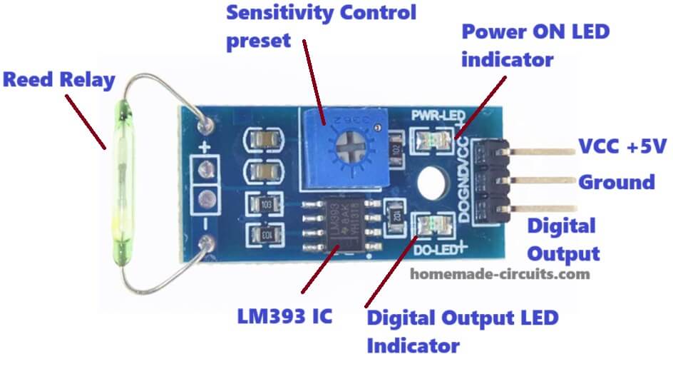
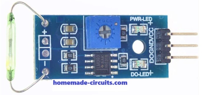
Let us Now Look at the Different Parts on the Board One by One
This module has many small components on it. Each part is doing its own small job and when all work together then it becomes smart magnet sensor.
1. Reed Switch Sensor (that long greenish glass tube)
This is the main device here, the actual sensor which detects the magnet. Inside that glass tube, there are two very small iron pieces which are like flexible metal blades. Normally these two blades are staying apart and not touching each other. But when you bring a magnet close to this glass tube then blades feel magnetic force and come closer to touch each other. The moment they touch, electricity can pass through them. That is why we call it a switch, because it becomes ON when magnet comes near.
Once the magnet is removed then those blades go back to their original position and become open again, so the switch becomes OFF. So this is how it works like an automatic switch based on magnet presence.
2. Blue Potentiometer (adjustable screw box)
This small blue box with screw on it is called a potentiometer. This is for adjusting the sensitivity of the module. What that means is, how close or how far the magnet has to be so that the sensor reacts to it. If you rotate the screw clockwise or anticlockwise, then trigger level will change. So you can decide how strong the magnet has to be or how close it must come to activate the output. You can tune it according to your need. If it is not detecting properly or detecting too fast then just adjust this screw slowly.
3. LM393 Comparator IC (black chip on the board)
Now this part is the brain of the module. This small black IC is called LM393, and it is doing a simple comparison job. It is always checking the signal coming from the reed switch and comparing it with a reference level which is set using the potentiometer. If the reed switch becomes ON and the magnetic field is strong enough then this IC gives a HIGH signal to the output pin. So it acts like a decision maker — it checks the input and says yes or no.
4. LED Indicators (two tiny lights)
There are two tiny LEDs on the board. One is called Power LED, and other is Signal LED.
- Power LED is always ON when the module is powered properly. This tells you that the module is alive and ready.
- Signal LED is OFF normally but when a magnet is detected and output goes HIGH, then this LED glows. This tells you visually that “yes magnet has come!”
So without any extra tools you can just see the LED and know if it is working or not.
5. Output Pins (3 pins on the left side)
This module gives three pins to connect with your circuit or microcontroller:
- VCC Pin – You connect this pin to 5V DC supply. Can be from Arduino or from some other 5V source.
- GND Pin – This one goes to ground. Must be connected to the same ground as the power supply.
- D0 Pin – This is the digital output pin. From here you will get HIGH or LOW depending on magnet presence. You connect this pin to Arduino digital pin to read the sensor status.
How This Module Works
Ok now imagine you are powering the module. You connect 5V to VCC and GND and the power LED glows. This tells you “ok, module is ready.”
Now nothing is near the sensor, so the reed switch inside is open, means no connection, so output is LOW.
Then you slowly bring a magnet close to the reed sensor. Now the two metal blades inside start feeling the magnetic field. When they feel it strongly then they touch each other and form a closed connection. This signal goes to LM393 IC.
LM393 now compares this signal with the level that is set by potentiometer. If the signal crosses that set level, then IC immediately sends out a HIGH signal from D0 output pin. At the same time, the signal LED glows.
Now you know magnet is detected.
After you remove the magnet, the reed blades open again, signal drops and the IC sends LOW at the output pin. LED also turns off.
So this whole process goes on like this – magnet near = ON, magnet far = OFF.
What We Can Do with This Reed Module?
There are so many uses of this sensor module. Wherever you want to detect something with magnet, you can use this:
- Use it on doors or windows to know if it is open or closed. Put sensor on frame and magnet on the moving door.
- Use it on bicycle wheels to count rotation or speed. Fix magnet on wheel and sensor on frame.
- Use it in burglar alarm, like when door opens, then magnet goes away and alarm triggers.
- Use it in robotics, for position sensing, like when magnet reaches sensor then something changes.
- Can also use in home automation like switching light when door opens.
So anywhere you want to know if two things are close or apart, this module can help.
How to Connect this Module to Arduino?
It is very easy and direct.
- VCC pin of module to 5V pin of Arduino.
- GND pin to GND pin of Arduino.
- D0 pin to any digital pin, like D2, D3, etc.
Then you just write a simple Arduino code to read the digital pin. If signal is HIGH then you know magnet is there. If LOW, then magnet is not there.
Here is a very simple example code you can try:
int reedPin = 2; // connect D0 here

void setup() {
  pinMode(reedPin, INPUT);
  Serial.begin(9600);
}

void loop() {
  int state = digitalRead(reedPin);
  if(state == HIGH){
    Serial.println("Yes, magnet is detected!");
  } else {
    Serial.println("No magnet here.");
  }
  delay(500);
}
This code will keep checking the sensor and printing in serial monitor whether magnet is there or not.
Some Extra Tips and Warnings
- If sensor is not triggering properly, try adjusting that blue screw slowly and test again.
- Don’t apply heavy force on the glass tube. It is fragile and can break easily.
- You can also add a 10K pull-down resistor on D0 pin if you want extra stability in signal.
- This module gives only digital output, not analog values.
- If you are using it with ESP8266 or ESP32, make sure the voltage levels are compatible.
Conclusion
So this is the full story of the reed switch sensor module. This sensor may look small but it is very powerful when you want to detect magnets without touching anything. It works silently and accurately. You can use it in hundreds of projects and it will do the job well.
Need Help? Please Leave a Comment! We value your input—Kindly keep it relevant to the above topic!