From a continuous source, battery, or vehicle alternator, it is possible to produce a 50 Hz voltage/pseudo-sinusoidal waveform, using this simple IC 4047 inverter circuit. The design is capable of operating many low-power devices that require a voltage of 220 V AC, typically supplied by the AC mains grid distribution network. The power of this module depends largely on the chosen transformer and, above all, on the continuous source's ability to supply the circuit without failure.
Working Principle of the circuit
Being able to power a device on the 220 V AC network when no mains AC power is available can be very convenient. We particularly think of campers, caravanners, fishermen, and motorists.
Although this simple setup does not provide a 100% clean sinusoidal wave, it can still satisfy many undemanding devices such as incandescent or fluorescent lighting, soldering irons, small motors, etc.
The power can reach up to 250 VA if the continuous source is strong enough and an adequate toroidal power transformer is chosen.
The power transistors are rated for 30 A, provided that a substantial heatsink is used.
We even suggest adding a small fan directly connected to the 220V output, which will prevent it from operating without a load.
Analysis of the Circuit Diagram
To obtain an alternating voltage from a DC source, the simplest solution is to use an inverted transformer: the low-voltage secondary winding has a center tap.
It is then sufficient to alternately supply power to the two windings to produce a symmetrical, but non-sinusoidal, variable voltage on the primary side if the low-voltage secondary winding is driven by a rectangular signal with steep edges.
Two complementary and opposite signals are required, and the CMOS integrated circuit with the reference 4047 is used to generate them, capable of either building an astable or monostable flip-flop.
The proposed diagram is shown in the figure below.
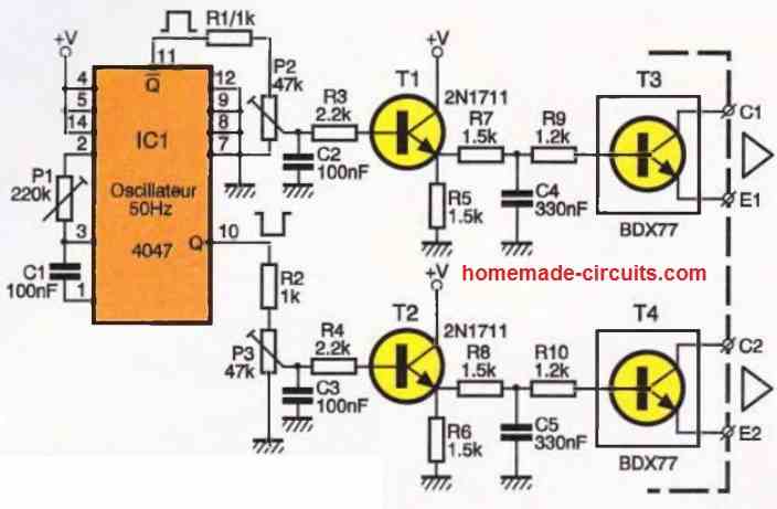
Of course, we will operate our circuit as an astable generator, ensuring a precise frequency of 50 Hz. This task is entrusted to components C1 and P1. Some pins of the IC1 circuit are connected to the ground or the positive supply, depending on our needs.
For more information, you will find an explanation in the appendix about the multiple possibilities of this practical little integrated circuit.
The symmetrical square voltages available at pins Q and Qdash (corresponding to terminals 10 and 11 of the circuit) are routed through resistors R1 and R2 to an adjustable element. Its role is to balance the amplitude of the two signals and facilitate the adjustment of the control module.
Note that the duty cycle will be exactly 50% by design. The sliders of elements P2 and P3 control the base of a 2N1711 transistor, which is responsible for driving the downstream power semiconductors.
Components R7, R9, C4, as well as R8, R16, and C5, form a coarse filter capable of smoothing out the signal angles to some extent.
This will allow us to create a "pseudo-sinusoidal" signal that will control the intermediate transistors T3 and T4 mounted on the small control board.
The BDX 77 models are rated for an emitter-collector voltage of 80V and a maximum peak current of 8A. They are delivered in a TO-220 package and will benefit from a heatsink.
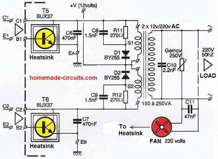
The secondary windings of the transformer do have a common point connected to the positive pole of the power supply.
The other end of the coils will receive the ground through the power transistors T5 and T6, a model not much larger than the famous 2N3055 but with a maximum peak current of around 30A in this case.
It is the NPN bipolar model with the reference BUX 39.
Diodes D1 and D2 absorb the unavoidable breakdown current produced at each interruption of the inductive element, which is the transformer.
The primary of the transformer, a toroidal model in this case, delivers a 50 Hz AC voltage.
The component labeled Gemov (or varistor) is placed between the output pins to clamp excessive voltage surges that may occur.
Two wires can also be tapped from the output to operate a fan directly powered by 220V, which will provide airflow to cool the transistor-heatsink assembly.
It is important to ensure that the voltage of the continuous source does not drop too much or be completely depleted in the case of a lead-acid battery.
It goes without saying that the input DC current can reach considerable values if, for example, a power of 200VA is desired. It would be prudent to include a robust series fuse, similar to those found in a household installation.
Construction
The creation of two printed circuit boards is necessary: the first one, shown in the figure below, is designed for the components described in the control module.
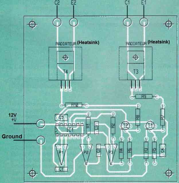
The layout is not very dense, but it is still recommended to use pre-sensitized copper-clad boards for reproduction.
After etching and rinsing, various drillings are carried out. Care must be taken to carefully mount transistors T3 and T4 on a small heatsink, which is directly attached to the epoxy board.
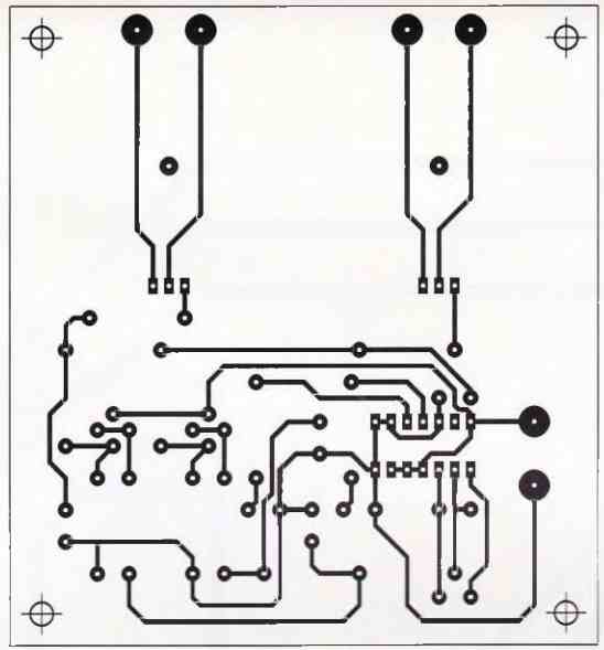
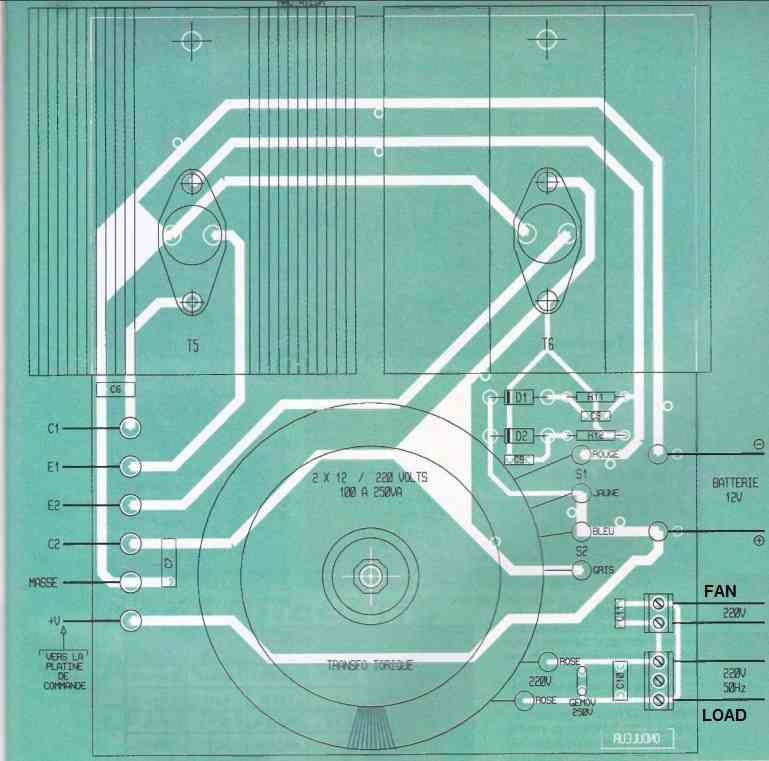
From this board, six wires will go to the significantly larger power module, and the track layout at a 1:1 scale can be found in the figure below.
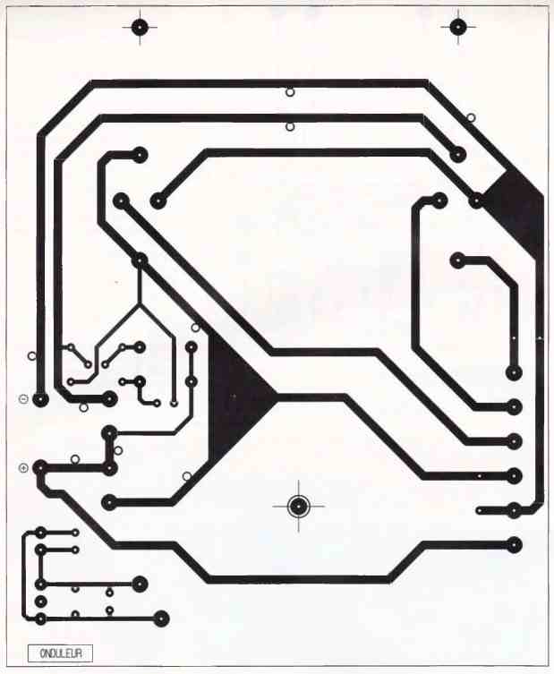
It should be noted that certain tracks on this simple IC 4047 inverter circuit board will carry high currents and require special treatment. We recommend soldering bare copper lengths, with a section of approximately 1.5 mm2, directly onto these tracks.
For example, electrician's copper wire with the insulation removed can be used. Care should also be taken to ensure all connections between the two boards, and in particular, to avoid reversing the wires.
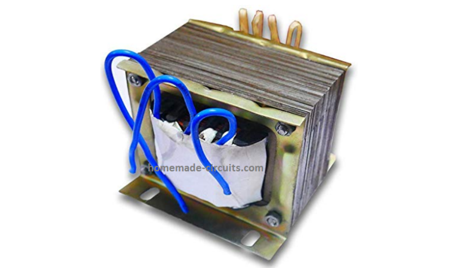
The transformer has six wires, with the two thinnest wires corresponding to the primary, and therefore our 220V output.
It is important to properly identify the other windings before soldering them permanently. This assembly can be housed in a sturdy, adequately ventilated metal enclosure.
How to Setup
We leave it to you to complete this final step for this simple IC 4047 inverter circuit. After a thorough check, the frequency can be adjusted to 50 Hz under no-load conditions using the adjustable preset P1, if you have an oscilloscope or frequency meter.
Otherwise, simply set this element to the midpoint position. The other two adjustable components are set to obtain a symmetrical signal in amplitude.
Initial tests can be performed using a simple socket where different power lamps can be connected. For resistive or slightly inductive loads, there should be no serious issues.
Proceed with caution when testing devices that typically require a true sinusoidal voltage.


Need Help? Please Leave a Comment! We value your input—Kindly keep it relevant to the above topic!