The EGS002 board is nothing but a combination of a microcontroller with a H-bridge driver like the IR2110. So if you are interested to build your own EGS002 equivalent board with exactly identical features, then you can do it using the instructions given in the following article.
So, here we are trying to build our own version of that popular EGS002 sine wave inverter module. But this one we will make using Arduino, and we will feed SPWM directly to a dual IR2110 based full H-bridge MOSFET driver.
And yes, we also got one opto coupler feedback section added for over voltage cut off safety. The whole thing looks solid and should work very close to EGS002.
Let us go step by step and understand how we have built it and how you can build this one too.
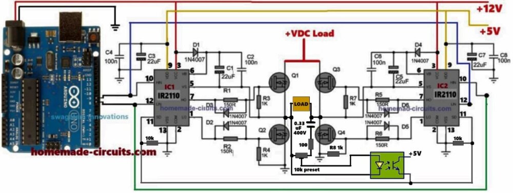
Circuit Diagram Overview
Referring to the image above, we can divide the whole design into 4 main blocks:
- Arduino SPWM Generator.
- Dual IR2110 H-Bridge Driver Stage.
- Power MOSFET Full Bridge Output.
- Opto Coupler Feedback for Over Voltage Cut-Off.
1. Arduino SPWM Generator Section
This is the brain of our inverter. So we take Arduino Uno and write a code that creates two sets of complementary SPWM signals. These signals are output from digital pins D9, D10 (for one half-bridge) and D11, D12 (for other half-bridge). These 4 signals go to the HIN and LIN pins of two IR2110 ICs.
We make sure these signals are sinusoidally modulated PWM signals, phase shifted by 180 degrees to drive the opposite legs of the H-bridge alternately. This gives rise to a full sine wave across the load after LC filtering.
2. Dual IR2110 Driver Stage
We use two IR2110 chips, one for each half of the H-bridge. They work like high side and low side MOSFET drivers.
- HIN and LIN inputs come from Arduino.
- HO and LO outputs go to MOSFET gates.
- High side bootstrap capacitor and diode (22uF + 1N4007) is used for high-side MOSFET gate drive
- Separate 12V for IR2110 VCC, and 5V logic from Arduino to the input pins
Each IR2110 drives 2 MOSFETs... one high side and one low side, in a half-bridge format.
3. MOSFET Full-Bridge Output Stage, How it is Connected
Now here we are using 4 power MOSFETs like IRF3205 or even IRF540 will also work good. We are calling them Q1, Q2, Q3, and Q4.
So Q1 and Q2, we are putting them on one side, that becomes one leg of the bridge. And Q3 and Q4 we are putting on the other side, that becomes the second leg of the full-bridge.
Now the load, like transformer primary or anything, we are not putting it directly with any one MOSFET, instead we are joining it right in the center between these two legs. That means one wire of the load goes to the middle point between Q1 and Q2 and the other wire goes to the middle point between Q3 and Q4.
Also, for the feedback opto coupler we are connecting one 0.33uF polyester capacitor, rated 400V, directly across the load output points. That capacitor helps to step down the current for the opto coupler LED.
And finally, in the opto-coupler stage which is used for feedback or over-voltage protection, we are taking one connection from the output and passing it through one 100 ohm resistor in series with one 10k preset or trimpot. This series path goes to the opto side. This resistor + preset combo allows us to set how much voltage the opto will see, and helps us adjust the protection level properly.
4. Opto Coupler Feedback Section
This part works like a protection. If output voltage becomes too high then the voltage across 10k preset rises, LED in opto coupler turns ON, and transistor conducts.
In the diagram, you can see the opto coupler transistor is configured with the SD (shut down) pins of the IR2110 ICs. In an event of a high voltage situation, the opto conducts and its transistor supplies the collector side +5V to the SD pins of the IR2110 IC causing their outputs to shut down instantaneously, enabling a quick restoration and stabilization of the output AC voltage.
If you want the shut down to happen at the Arduino side, then you can configure the opto stage in the following manner.
This transistor pulls down the Arduino pin (say A0 or D2) and stops SPWM generation. So output shuts down if over voltage happens.
You can adjust the 10k preset to set the cutoff threshold.
How It Works Like EGS002
EGS002 also uses SPWM for creating sine wave from a full bridge stage. It has feedback, protection, dead time, frequency, etc., all done inside EGS002 chip.
Here we are doing same with Arduino + IR2110. Arduino creates SPWM + dead time logic, IR2110 gives gate drive with isolation between logic and power, and opto gives protection.
So overall this is a full EGS002 replacement but done with discrete and open-source method.
Construction Steps
- Take a clean double-sided PCB or general purpose board.
- First place and solder both IR2110 ICs with all boot capacitors, diodes, resistors.
- Connect the MOSFETs close to the IR2110s using thick tracks or wires.
- Keep Arduino mounted on a separate PCB and connect pins D9–D12 to IR2110 HIN, LIN pins.
- Give 12V to IR2110, 5V to Arduino.
- Build the output LC filter if needed (optional).
- Add opto coupler circuit on output side with series 100 ohm and preset.
- Check and test everything with small DC input first.
Download Arduino SPWM Code:
If you want to know how optimize and change the above Arduino SPWM code parameters, you can take the help of this Sine Table Calculator.
Features of Our Design
| Feature | Details |
|---|---|
| SPWM Generator | Arduino UNO (custom modifiable) |
| Gate Driver | Dual IR2110 IC |
| Output Stage | Full Bridge 4x N-channel MOSFETs |
| Over Voltage Cut-off | Opto Coupler Feedback |
| Output Waveform | Pure Sine Wave via SPWM |
| Input Supply | 12V for IR2110, High Voltage DC for load |
| Output Voltage | 220V RMS AC after LC Filter |
Conclusion
So this one is like our homemade EGS002 board. We used Arduino brain to generate sine wave with SPWM and IR2110 muscles to drive MOSFETs. Then one opto eye watches the output voltage and stops everything when danger comes.
You can fully control frequency, waveform shape, duty, etc., through Arduino. It is open source, flexible, and scalable. You can easily build this with off-the-shelf parts.


Comments
I’m trying to build a similar inverter that converts 12 V DC to 12 V AC.
I’ve already done it successfully using an EGS002 SPWM module with a 0.3 mH + 3 µF LC filter, and it produces a nice clean 50 Hz sine.
The EGS002 uses a 23.4 kHz switching frequency and I’m wondering how an Arduino could achieve the same thing.
You can try the following concept to convert a 12V DC into 12V AC sine wave:
https://www.homemade-circuits.com/arduino-pure-sine-wave-inverter-circuit/
Use only one section of the code, and use a BJT booster stage at the output of the Arduino to boost the Arduino 5V to 12V sine wave…
I’m trying to build a similar inverter that converts 12 V DC to 12 V AC.
I’ve already done it successfully using an EGS002 SPWM module with a 0.3 mH + 3 µF LC filter, and it produces a nice clean 50 Hz sine.
The EGS002 uses a 23.4 kHz switching frequency and I’m wondering how an Arduino could achieve the same thing.
I used the same code you published in the other project (also Arduino based inverter) but I’m getting a square wave. Is it because the switching frequency is not 23.4kHz?
You are getting square waves because you are not using a filter at the output.
Please try an LC filter such as this:
https://www.homemade-circuits.com/inverter-lc-filter-calculator/
can I use EGS002 module ? and igbt for 3kw load?
Yes, you can use them both..
I would like to know how to write code for IC ATM Mega 8. Use the spwm signal to use in driving the MOSFET. The details are
How? Thank you
There are many online courses which you can follow and learn it….