This single MOSFET solid-state relay SSR circuit is a very simple where you can drive an AC load like a lamp, motor, or any oter AC load, through a small DC control voltage.
We use only one IRF840 MOSFET to switch the 220V AC load, and we do this with some clever diode bridge arrangement, one BC547 stage, one PC817 optocoupler, one zener, some resistors, and one RC snubber. So we get a low cost SSR that works for light duty load.
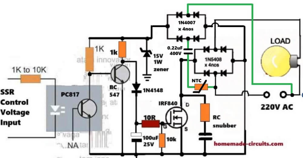
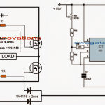
Full Circuit Diagram
Audio/Video Representation
Why We Use PC817
We use PC817 because we want total isolation between control side and the dangerous AC side, so when you apply any small input voltage from 1V to 12V to the SSR input, then the PC817 LED lights up and the internal transistor inside PC817 conducts.
That transistor pulls the external BC547 base low, and then we get the MOSFET gate biasing started. So we stay totally safe from the 220V AC because of this isolation.
How The BC547 Works
We see that BC547 is used like a small level shifting and shaping transistor. When PC817 activates through an external control voltage then it causes the BC547 turn off. When this happens then positive supply is able to enter through its collector 1K and the 1N4148 to reach the MOSFET gate network.
The BC547 also makes sure that the gate capacitor 100uF charges and discharges slowly so that the MOSFET does not switch too fast and gets a clean DC for the switching. This protects the MOSFET from sudden AC peaks. So we now understand that BC547 is doing the job of a driver and a buffer.
Why We Have The Zener
We put a 15V 1W zener because we want the gate voltage of IRF840 to never cross around 12V to 15V.
If the AC peak becomes large due to the 68K 2 watt resistor dropping current, then the zener clamps it to a safe level, so that the MOSFET gate gets enough voltage to switch strongly but never too much to break down the gate oxide. So the zener is for MOSFET gate safety.
Role Of The 68K 2 Watt Resistor
You see this is the main high voltage dropping resistor, which takes the 220V AC peak and drops it down to a small current that charges the 100uF capacitor via the diodes whenever the BC547 is turned off with an input control signal.
So this resistor feeds the gate driver with limited current. Because it is handling AC peaks, so we use 2 watt, just to protect it and we safely develop the gate DC supply for the MOSFET.
Why We Use The 1N5408 Diode Bridge
We put 4 * 1N5408 diodes in bridge form so that the MOSFET always sees a DC polarity across its drain and source even though the load is AC.
This is important because MOSFET can switch DC smoothly but in AC the polarity keeps reversing, so the diode bridge takes AC from the mains and gives DC polarity across MOSFET.
So whenever the MOSFET turns ON, then the bridge allows current in both half cycles to the load causing the lamp or load sees AC normally.
How The MOSFET Switches AC Load
We put IRF840 in the DC path that comes out from the diode bridge, so when BC547 sends voltage to the gate, then the MOSFET starts conducting.
The MOSFET completes the DC route inside the diode bridge and so AC starts flowing to the load.
When the gate voltage goes low then MOSFET stops, and the AC load switches OFF, so that shows we we are simply controlling AC with a DC MOSFET.
Why We Add The RC Snubber
We add the RC snubber to absorb sudden voltage spikes across the MOSFET because AC loads can create a lot of noise, especially inductive loads, so the snubber protects the MOSFET from high dv/dt and keeps the switching smooth, keeping the circuit safe.
How The Circuit Responds To Control Voltage
Now let us say you apply 5V or 12V to the SSR input pins, then PC817 LED glows, this causes the PC817 transistor to conduct.
This pulls the BC547 base to ground by the opto-coupler internal BJT.
This allows the +15V 100 Hz DC to enter through the 1N4148 and feed the 100uF capacitor and the gate resistor network where it is converterd to a stable 15V DC for the MOSFET gate.
Then the IRF840 gate rises to around 10V to 12V regulated by the zener and the MOSFET switches ON.
After this the diode bridge routes AC to the load.
When you remove the control voltage then PC817 LED switches OFF and everything collapses, the gate capacitor slowly discharges, and the MOSFET shuts OFF.
Practical Use
You can use this SSR to switch lamps, CFL lamps, or small heaters. It is not for heavy inductive motors because IRF840 cannot handle very large current and inductive spikes without powerful snubbers, but for moderate loads it works very nicely. It is cheap and safe. Of course you can upgrade the MOSFET with higher rating or IGBT for handling extreme high loads.
Important Safety
Always remember that this circuit uses 220V AC, so if you touch anything wrong, then you get severe shock.
So we always build it inside a fully insulated box and we keep proper spacing on PCB. We must never touch the circuit when AC is connected. So we protect ourselves always.
Conclusion
So now we understand everything about this single MOSFET SSR design. We see how we use simple components like PC817, BC547, IRF840, zener, big resistor and diode bridge to create a cheap AC switching circuit. If you have any questions please feel free to ask in the comments section.
Parts List (BOM)
| Part Name | Specification | Quantity |
| PC817 | Optocoupler, standard type | 1 |
| BC547 | NPN transistor | 1 |
| IRF840 | MOSFET, 500V, 8A | 1 |
| 1K Resistor | 1/4 watt | 2 |
| 68K Resistor | 2 watt | 1 |
| 10K Resistor | 1/4 watt | 1 |
| 10R Resistor | 1/4 watt | 1 |
| 15V Zener Diode | 1 watt | 1 |
| 1N4148 Diode | Small signal diode | 1 |
| 1N5408 Diode | 3A rectifier diode | 4 |
| 100uF Capacitor | 25V electrolytic | 1 |
| RC Snubber Resistor | 100 ohm 1 watt (approx) | 1 |
| RC Snubber Capacitor | 0.1uF 400V (approx) | 1 |
| AC Load | 220V lamp or small appliance | 1 |


Comments
hi sir, sir can we use 12 volt 1 watt zenor instead of 15v zenor?
Hi Ghulam, yes 12V will also work…