The CD4541B is a CMOS programmable timer IC, and we use it where long delay interval is needed for a load, and also for jobs like frequency division, or timing pulse work. And all this happens with only just a few outside parts, not much around it.
With ordinary IC 555, when delay becomes too long then trouble starts because capacitor value must go very high and that becomes bulky, leakage also comes.
Now CD4541 handles this differently, since inside it already has one RC oscillator, one 16-stage binary divider, output selecting section, and reset control...
Because of that, small capacitor can still give long delays, from milliseconds and then going up to many hours which is why people still use it.
Basic Application Diagram
Main Features of the CD4541B
Main features are simple, supply can go up to 18V practical, 20V maximum, oscillator is already inside. External clock also possible, divider stages are inside.
Output can be selected, timer mode or divider mode both there.
Auto reset and manual reset both given, and output polarity also can be changed.
CMOS output is symmetrical, so it can directly handle several TTL loads also.
Internal Working Principle
Inside the IC, first oscillator makes pulses, then those pulses enter divider, and divider reduces frequency by selected stage, like 2^8, 2^10, 2^13, or 2^16, so therefore delay becomes long without needing huge RC parts.
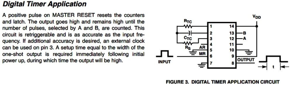
Package Type and Pin Configuration
- This IC comes in 14 pin package.
- Pin 1 is RTC, where timing resistor goes.
- Pin 2 is CTC, where timing capacitor goes.
- Pin 3 is RS, which is for series resistor, oscillator stability side.
- Pin 4 no connection.
- Pin 5 auto reset control.
- Pin 6 master reset input, and if positive pulse comes then counter resets.
- Pin 7 ground.
- Pin 8 output.
- Pin 9 selects Q or Q̅.
- Pin 10 selects mode.
- Pin 11 no connection.
- Pin 12 A select input.
- Pin 13 B select input.
- Pin 14 positive supply, and supply can stay from 3V up to 18V practical.
Oscillator Frequency Formula
Timing frequency comes from:
f = 1 / (2.3 * RTC * CTC)
Here f means oscillator frequency, RTC timing resistor, CTC timing capacitor.
This works properly when frequency stays between 1 kHz and 100 kHz, RS must be 10k or more, and usually RS near 2 * RTC gives stable side.
Importance of RS Resistor
Many beginners leave RS out, but that resistor matters, because it limits current into oscillator input and keeps waveform steady, and if RS is missing then timing can drift, oscillator may shake, and long delay becomes less accurate.
Divider Selection Through Pins A and B
- Pins A and B choose divider stage.
- If A = 0 and B = 0 then divide by 2^13.
- If A = 0 and B = 1 then divide by 2^16.
- If A = 1 and B = 0 then divide by 2^8.
- If A = 1 and B = 1 then divide by 2^10.
Delay Calculation Formula
So delay becomes:
Delay = Divider / f
If oscillator frequency is 1000 Hz and divider selected is 2^16, then delay becomes 65536 / 1000, nearly 65.5 seconds.
Operating Modes of the IC
There are two working modes.
If MODE pin goes HIGH, then output keeps running as square wave continuously, so output frequency becomes:
fout = f / 2^N
That is useful for pulse making, clock making, divider work.
If MODE pin goes LOW, then after reset output changes only once after full count finishes, so this mode fits long delay switching and alarm type circuits.
One Practical 1-Minute Timer Circuit
For one practical 24 hour timer circuit...
Component Values for About 24 Hours
Use:
- RTC = 1MΩ
- CTC = 0.56uF
- RS = 2.2MΩ
Then:
f ≈ 0.78 Hz
Delay ≈ 65536 / 0.78
≈ 84000 seconds
≈ 23.3 hours
Very close to 24 hours.
Auto Reset Function (Pin 5)
Pin 5 controls auto reset.
If pin 5 stays LOW, then IC starts timing as soon as power comes.
If pin 5 goes HIGH, then timing waits until manual reset pulse comes.
Datasheet also notes that auto reset takes some extra current, so if low power is needed then manual reset is better.
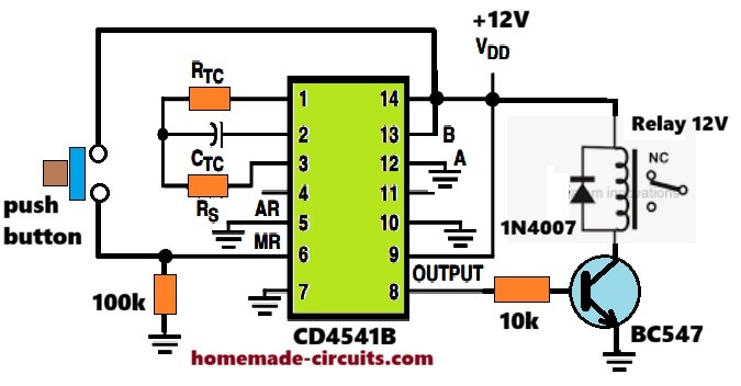
Master Reset Function (Pin 6)
Pin 6 is master reset.
If positive pulse comes there, then divider clears, timing clears, and count starts again.
This helps in relay timing, repeat cycles, machine control side.
Output Polarity Selection (Pin 9)
Pin 9 chooses output polarity.
If pin 9 LOW, then normal Q output.
If pin 9 HIGH, then inverted Q̅ output.
So delayed ON or delayed OFF can be chosen without extra inverter.
Why CD4541 Is Better Than IC 555 for Long Delays
For long delays, CD4541 stays better than NE555, because 555 usually needs huge capacitor, leakage error comes, long stability becomes poor, but here small RC enters divider and long delay comes clean.
That gives better stability and smaller capacitor size.
Common Applications of CD4541
Common uses are relay delay timer, automatic light timer, battery saver, irrigation controller, inverter startup delay, watchdog timer, and long pulse generator.
PCB Layout Precautions
For PCB work, timing capacitor should stay close to IC, RTC and CTC lines must stay clean, leakage around pins should be avoided, and stable capacitor like polyester or NP0 ceramic is better.
Electrolytic capacitor should not be used if precise timing is wanted.
Timing Accuracy and Tolerance
One practical limit stays there, since timing depends on RC tolerance, actual delay may shift by ±5% to ±15%, so if accurate delay is needed then resistor and capacitor should be precision type.
Why CD4541 Is Still Popular Today
Even now this IC remains useful, because no programming needed, standby current is very low, reliability stays good, and long delay comes easily, which is why industrial timer circuits still keep using it.
Source: ti.com


