The simple LED oscilloscope circuit I have explained in this article can be used for analyzing low frequency waveform through a 10 x 10 LED matrix display.
Due to the involvement of only 100 LEDs in the display board, the resolution is low, and the waveform display clarity is not so impressive. Yet, this LED oscilloscope circuit can perform reasonably well for analyzing basic low frequency waveform.
Circuit Description
The heart of the circuit are the two ICs, IC2, and IC3, which are IC LM3915 and IC 4017 respectively.
Before going into the details of the proposed LED oscilloscope circuit, it would be first important to learn about the brief functioning details these two ICs.
LM3915 Functioning
The LM3915 is a dot/bar display driver IC.
The outputs of this IC activates sequentially from pin#1 towards pin#10, one after the other, in response to an increasing voltage level across its pin#5 and ground.
So when a rising potential is applied at pin#5, a low logic shifts correspondingly from pin#1 towards pin#10, in response to this rising potential.
If LEDs are connected across pin#1 and pin#10 with their common anodes connected to the positive line, then these LEDs would illuminate sequentially from pin#1 until pin#10, and vice versa, in response to a rising, falling voltage across pin#5 and ground of the IC.
When the pin#9 of IC is unconnected, all the output sequence without latching creating a dot like movement for the connected LEDs.
Whereas, when the pin#9 is connected to the positive supply, the output pins of the IC sequence in a latching mode, so that the pinouts advance sequentially and also latch one after the other creating a rising bar like effect on the connected LEDs.
In this LED oscilloscope circuit, the IC LM3915 is configured to detect the rising/falling amplitude voltage of an input waveform signal, so that it produces a correspondingly shifting outputs, in the form of a low logic moving up/down across the LED matrix.
IC 4017 Functioning
Technically, the IC 4017 is a Johnson decade counter with 10 decoded outputs.
Just like the IC LM3915, the IC 4017 also exhibits a sequentially activating outputs from pin#3 towards pin#11, however, this sequential shifting of the outputs is in response to ON/OFF pulses at it pin#14.
Meaning, when a first positive pulse hits pin#14, a logic high output shifts from pin#3 to pin#2, when the second pulse arrives at pin#14, the logic high pulse shifts from pin#2 to pin#4....this sequential shifting of the logic high continues until it reaches pin#11, when the IC resets, and the logic high reverts to pin#3 for a fresh cycle.
In this LED oscilloscope article, the IC 4017 is configured to produce a time base generator, which corresponds to the period of an input waveform to be analyzed.
How the LED Oscilloscope Works
The complete circuit schematic of the simple LED oscilloscope can be witnessed in the following diagram:
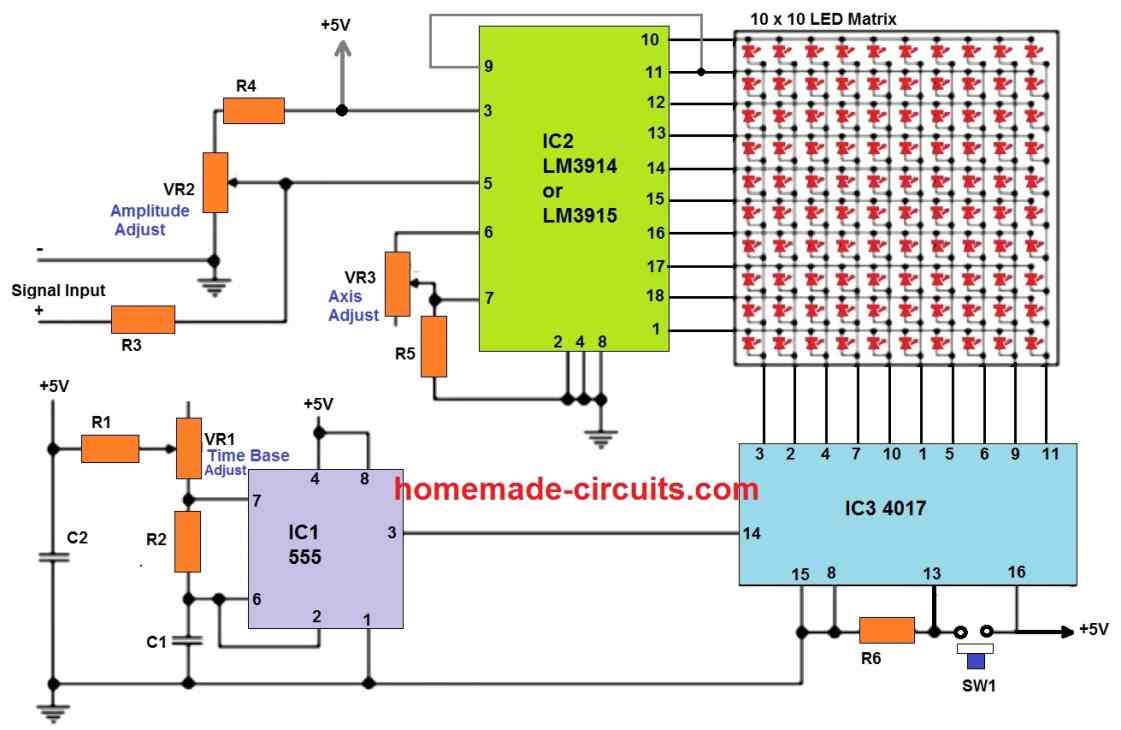
Parts List
- R1 = 150 ohms
- R2, R5 = 1k,
- R3, R6 = 10k
- R4 = 18k
- VR1 = 470k pot
- VR2 = 4k7 pot
- VR3 = 2k2 pot
- C1 = 47 nF
- C2 = 10 nF
- SW1 = push to ON switch (microswitch)
- IC1 = Any 555 IC
- IC2 = LM3915, or LM3914
- IC3 = Any 4017 IC
- All LEDs are 5 mm RED or GREEN, 20 mA Type
As discussed above, the IC LM3915 detects the oscillating voltage of a waveform, and correspondingly generates a low logic across its outputs, which shift up/down sequentially in response to the amplitude of the waveform.
This up/down shifting happens across the Y-axis.
However, to trace the waveform we need to enable this amplitude to sweep across the X-axis, so that the waveform becomes visible across the LED matrix.
This process is accomplished by the IC 4017 outputs.
Since the IC 4017 outputs generate a shifting logic high, and the IC LM3915 outputs generate a shifting logic low, all the anodes of the LEDs are joined with the IC 4017 outputs, and all the cathodes of the LEDs are hooked up with the IC LM3915 outputs.
This allows the IC 4017 outputs to work like a time base generator, while the outputs of the IC LM3915 works like a signal modulator.
The IC 4017 can be also imagined like a carrier signal generator as we have in a AM/FM transmitter waveform.
Now, as discussed earlier, the outputs of the IC 4017 will shift sequentially only in response to an oscillating pulse applied across its pin#14.
This is achieved by the IC 555 circuit which is configured as a astable multivibrator.
The oscillating pulse generated at pin#3 of the IC 555 is applied to pin#14 of the IC 4017, which causes the outputs of the IC 4017 to produce a sequentially running high logic from its pin#3 towards pin#11.
How Waveform Pattern is Generated on the LED Matrix
Now let's analyze what happens when an external waveform signal is applied across pin#5 of the IC LM3915.
The LEDs on the Y-axis are controlled by the LM3915 outputs, which indicate the amplitude of the waveform.
The LEDs on the X-axis are controlled by the IC 4017 outputs, which indicate the time base frequency of the oscilloscope.
The IC LM3915 detects the amplitude of the waveform, and generates a corespondingly shifting up and down low logic across the connected LEDs.
Since the 4017 also supplies a shifting logic with some frequency, the up/down LED illumination on the Y-axis from the LM3915 outputs is swept across the X-axis, so that it corresponds to the time period of the waveform.
This allows a sweeping waveform pattern to be simulated on the 10 x 10 LED matrix.
The speed at which the outputs of the IC 4017 shift determines the direction of the waveform.
If the speed is less than the time period of the waveform, the LED waveform appears to move from right to left, and when the speed is higher than the waveform time period, the LED waveform appears to move from left to right.
This speed determines the time base frequency of the IC 4017 which is generated by the IC 555 astable, and can be adjusted with the help of the VR1 variable resistor.
Oscilloscope Adjustments
All oscilloscopes have three fundamental adjustments through potentiometers, the time base frequency adjustment, amplitude or the voltage scale adjustment, and Y-axis position adjustment.
These adjustments allow the waveform pattern on the screen to be correctly optimized for facilitating proper analysis of the waveform.
The discussed LED oscilloscope circuit also includes these three basic adjustment features.
The pot VR1 allows the adjustment of the time base frequency, across the IC 4017 outputs.
The pot VR2 adjusts the voltage level of the waveform on pin#5 of the LM3915, and thus helps to adjust the amplitude voltage scale of the waveform on the LED display.
VR3 helps to adjust the Y-axis shift on the 10 x 10 LED matrix display.
The switch SW1 can be pressed to disable the IC 4017 time base momentarily, preventing the horizontal sweeping of the waveform.
This concludes the circuit description of our LED oscilloscope. If you have any questions or suggestions, regarding the circuit, you can feel free to express them through comments.

Comments
Hey there Sugatam,
I built this same oscilloscope 25 years ago and had a lot of fun and it is still one of my best memories building this circuit. I have an idea:
By paralleling 2 or more LM3914s together and also the same number of 4017s and increasing the clock of the 555 to sweep the columns to increase the sampling frequency of the input frequency pattern, we can make a larger screen with higher resolution.
What do you think?
Great to know about your past experience with LED scopes, Alireza!
Yes, more number of cascaded ICs will proportionately enhance the resolution of the screen
He there Sugatam,
By paralleling 2 or more LM3914s together and also the same number of 4017s and increasing the 555 clock to sweep the columns to increase the sampling of the input frequency pattern, a larger screen with higher resolution can be made.
What do you think?
Thank you Alireza, that can be definitely done, cascading more number of ICs will proportionately increase the resolution of the screen and the waveform accuracy…
I’m highly impressed of your innovation sir swagatam. Can I use two metrix LED. to have fool wave display? How?. Thanks alot sir.
Thank you Adams, Glad you found the post helpful
The number of LEDs shown in the diagram cannot be increased because the 10 x 10 output pins if the two ICs can accommodate only a matrix of 10 X 10 LEDs.
Sir, Can this oscilloscope be used to align and test tube/valve radios. Many thanks and kind regards, Ben Raghubeer.
Hi Ben, sorry, I do not have any ideas about this subject!
i will try to make this circuit
As I think it is easy to use prefabricated 8X8 Led Matrix,
My question is how to connect two pcs. Of cascaded CD 4017
In order to show the waveform on two adjacent 8×8 led matrix
You can try this circuit:
https://www.homemade-circuits.com/wp-content/uploads/2022/05/18-LED-chaser-circuit.jpg
You can not measure MHz signals as the maximum waveform you can measure is limited by the switching speed of LM3914 which is about 200 KHz max.
Very cool circuit, when you say low frequency, I didn’t see a range, thanks
Art
Thank you, actually it seems the device should be capable of measuring high frequencies also, simply by increasing the frequency of the IC 555. You can even replace IC 555 oscillator with a CMOS oscillator and measure signals in MHz
That’s to cool, thanks after I build two more projects, I am going to work on this one, I like this one very diferent, who knows with a better array LED maybe I could replace a scope, just kidding. Thanks
Sure, let us know if you happen to build it successfully. That may be actually possible, by cascading a few more ICs together you can upgrade the LED matrix and improve the resolution of the display to a great extent.