• Skip to main content
  • Skip to primary sidebar

Homemade Circuit Projects

Need circuit help? Post them in the comments! I've answered over 50,000!

Blog | Categories | About | Contact | Calculators-online
You are here: Home / Datasheets and Components / IC 4016 Datasheet, Pinout Function


IC 4016 Datasheet, Pinout Function

Last Updated on February 27, 2023 by Swagatam Leave a Comment

IC 4016 is a CMOS-based quad bilateral switch integrated circuit (IC). It may be used for a variety of purposes, including waveform generation, voltage-controlled oscillator, switching of audio and video signals, and controlling analogue and digital signals (VCO).

Table of Contents
  • Electrical Characteristics:
  • Pin Configuration:
  • Features:
  • Applications:
  • Package Details:
  • Recommended Operating Conditions:

A thorough datasheet for the IC 4016 is I have explained below:

Electrical Characteristics:

  • Supply Voltage Range: 3V to 18V
  • Quiescent Current: 10µA
  • Maximum Operating Frequency: 50 MHz
  • Maximum Output Current: 25mA
  • Maximum Power Dissipation: 500mW
  • Maximum Operating Temperature: -55°C to +125°C

Pin Configuration:

The IC 4016 has a total of 14 pins, which are numbered as follows:

Pin#14 is positive supply of the IC, and pin#7 is the ground supply of the IC, both of these pins are not shown in the diagram below.

warning message: electricity is dangerous, proceed with caution
4016 IC

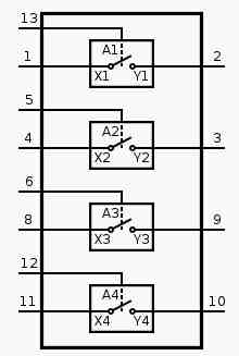
As shown in the above figure, the pinout functioning of the IC 4016 can be understood with the following points:

There are 4 digital gates inside the IC 4016 which work like electronic switches.

Each of these gates has a bilateral input/output pinouts (X, Y) and a control pinout (A).

The signal which needs to be switched ON or OFF is sent across these input/output pinouts, for example X1, and Y1.

This signal remains switched OFF and cannot pass across the input/output terminals, until a switching positive input voltage is supplied at the control pin of the switch.

For example, lets looks at the first switch module having input/ouputs pinout numbers 1 and 2. For this switch pin number 13 is the control input.

Therefore, as long as a positive voltage is not applied to pin#13, the signal applied across pin#1 and pin#2 will never conduct. As soon as a positive supply is fed to pin#13, the signal across pin#1 and pin#2 will start flowing.

The same working principle is true for the remaining 3 switches of the IC 4016.

Features:

  • Low Quiescent Current
  • High Noise Immunity
  • High Speed Switching
  • Wide Supply Voltage Range
  • Easy to Use and Implement
  • Low Power Consumption

Applications:

  • Audio and Video Signal Switching
  • Waveform Generation
  • Voltage-Controlled Oscillator (VCO)
  • Signal Modulation and Demodulation
  • Digital Logic Level Shifting
  • Multiplexing and Demultiplexing

Package Details:

The IC 4016 is available in different package types such as PDIP, SOIC, and TSSOP. The package details are as follows:

PDIP: 14-Pin Plastic Dual In-Line Package SOIC: 14-Pin Small Outline Integrated Circuit Package TSSOP: 14-Pin Thin Shrink Small Outline Package

Recommended Operating Conditions:

  • Supply Voltage Range: 3V to 18V
  • Input Voltage Range: 0V to VDD
  • Operating Temperature Range: -55°C to +125°C

Note: These values are subject to change based on manufacturer's specifications.

In conclusion, the IC 4016 is a versatile and a reliable IC, which could be employed in a variety of electrical circuits.

You'll also like:

  • 1.  AMS1117 1A LDO Voltage Regulator IC – 3.3V, 1.8V, 2.5V, 5V Regulators
  • 2.  Electronic Component Buying Guide for New Hobbyists
  • 3.  2N3906 Datasheet [40V, 200 mA, PNP Transistor]
  • 4.  BC547 Transistor Datasheet [45V, 100mA NPN Transistor]
  • 5.  IRFZ44 Datasheet [55V 49 Amp N-channel MOSFET]
  • 6.  220V Solid State Relay (SSR) Circuit using Triac and OptoCoupler

Filed Under: Datasheets and Components Tagged With: 4016, Datasheet, function, Pinout

About Swagatam

I am an electronics engineer and doing practical hands-on work from more than 15 years now. Building real circuits, testing them and also making PCB layouts by myself. I really love doing all these things like inventing something new, designing electronics and also helping other people like hobby guys who want to make their own cool circuits at home.

And that is the main reason why I started this website homemade-circuits.com, to share different types of circuit ideas..

If you are having any kind of doubt or question related to circuits then just write down your question in the comment box below, I am like always checking, so I guarantee I will reply you for sure!

Previous Post: « IC 4013 Datasheet, Pinout Details
Next Post: IC 4018 Datasheet, Pinout Function Explained »

Reader Interactions

Need Help? Please Leave a Comment! We value your input—Kindly keep it relevant to the above topic! Cancel reply

Your email address will not be published. Required fields are marked *

Primary Sidebar

circuit simulator image

Subscribe to New Posts


Categories

  • Arduino Projects (89)
  • Audio and Amplifier Projects (132)
  • Automation Projects (17)
  • Automobile Electronics (101)
  • Battery Charger Circuits (83)
  • Datasheets and Components (104)
  • Electronics Theory (143)
  • Free Energy (37)
  • Games and Sports Projects (11)
  • Grid and 3-Phase (19)
  • Health related Projects (25)
  • Home Electrical Circuits (12)
  • Indicator Circuits (14)
  • Inverter Circuits (88)
  • Lamps and Lights (142)
  • Meters and Testers (69)
  • Mini Projects (46)
  • Motor Controller (64)
  • Oscillator Circuits (27)
  • Pets and Pests (15)
  • Power Supply Circuits (108)
  • Remote Control Circuits (50)
  • Security and Alarm (64)
  • Sensors and Detectors (101)
  • Solar Controller Circuits (59)
  • Temperature Controllers (42)
  • Timer and Delay Relay (49)
  • Transmitter Circuits (29)
  • Voltage Control and Protection (39)
  • Water Controller (36)


Other Links

  • Privacy Policy
  • Cookie Policy
  • Disclaimer
  • Copyright
  • Videos
  • Sitemap


People also Search

555 Circuits | 741 Circuits | LM324 Circuits | LM338 Circuits | 4017 Circuits | Ultrasonic Projects | SMPS Projects | Christmas Projects | MOSFETs | Radio Circuits | Laser Circuits | PIR Projects |

Social Profiles

  • Twitter
  • YouTube
  • Instagram
  • Pinterest
  • My Facebook-Page
  • Quora
  • Stack Exchange
  • Linkedin


  • Recent Comments

    • Swagatam on How Shunt Regulator TL431 Works, Datasheet, Application
    • SA on How Shunt Regulator TL431 Works, Datasheet, Application
    • Farmtech on Free Energy Generator Circuit – The N-Machine
    • Nitesh Agrawal on How to Design Simple LED Driver Circuits
    • Swagatam on How to Design Simple LED Driver Circuits

    © 2025 · Swagatam Innovations