In this article I have explained the circuit implementation of an interesting concept of converting physical energy into electricity. Here I have explained a simple method of converting or channelizing the wasted gym workout energy into useful electrical energy. The idea was requested by one of the keen members of this blog, let's know more:
Technical Specifications:
Hello sir,
I'm final year ECE student.
I'm willing to generate power to my college gym.
I have some idea related to that. so I need your some idea relate to that.
How can i make power through the weight related exercise machine? we can't use piezo electric crystal.
I need some idea. and one more thing I'll tell my procedure for that if any mistake arise correct me.
1.Generate AC power through generator
2.Gives to the rectifier
3.Save power in battery
4.Use inverter for commercial use.
The Design
Implementing the above concept is actually very straightforward as the input energy source is definite and consistent.
While working out in a gym, the participants are much eager to donate their physical power either to shed-of extra weight or for enhancing muscle growth. Therefore, anyway this power is meant for wasting which makes the concept much easier to achieve.
We all know that the most simplest way of converting a mechanical force into electricity is through a motor, or by using the force for spinning the motor and acquiring electricity from the output wires of the motor.
The above principle can be every effectively employed here as well.
All the weight training equipment in a gym which incorporate pulley/rope and suspended weight mechanism can be transformed into electricity generating machines.
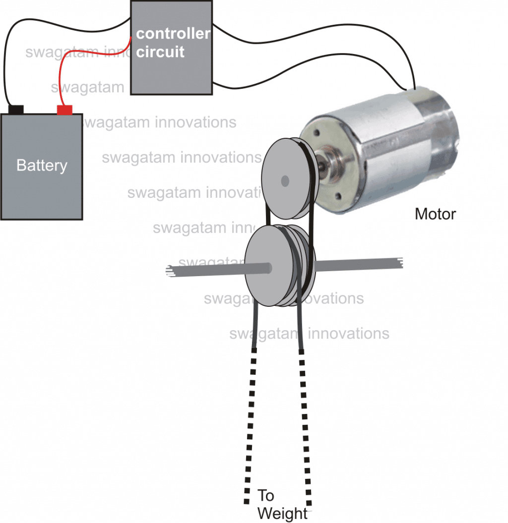
As shown in the figure below, an arrangement may be fabricated where with an additional rope pulley mechanism a simple permanent magnet type motor can be integrated with the existing weight training machine.
When any member pulls and uses the machine while working out, the motor also gets rotated in accordance, in a push pull manner.
The above movement induces the required electromotive energy across the motor output wires which is appropriately processed inside the rectifier/controller circuit and finally delivered across the connected battery for charging it.
Another point may be witnessed here, with a discharged battery connected, the motor would be subjected to greater torque making the mechanism stiffer.
This would hopefully make the whole thing more challenging and enjoyable for our "body builders".
The motor pulley should be much smaller in size compared to the machine pulley, so that the rotation ratio favors maximum number of rotations over the motor pulley and helps to generate optimal power from the motor.
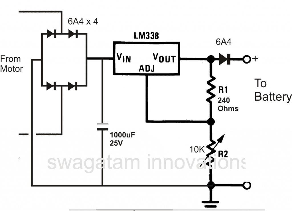
A simple charger/controller is shown below, which can be employed for this application too. The circuit utilizes the well known IC LM338.
The "push-pull" voltage from the motor, or the alternating voltage from the motor is first rectified by the four diodes, filtered by the capacitor and regulated to the desired battery voltage by the IC LM338 circuit.


Comments
please can you send me more detailles about this work ?
Please let me know what details you need, I will try to help!
I want to do this experience with small equipement and i don’t how to do it from A to Z
You will have to install the pulley wheel mechanism, and integrate it with a permanent magnet DC motor, that’s all.
First complete this setup then we can discuss about the regulator.
Do you have a DC motor with you?
ok, what after ?
Why can’t this work with piezoelectric energy harvesters?
https://www.mouser.in/ProductDetail/Mide/S118-J1SS-1808YB?qs=9r4v7xj2LnlK6yfRfh%252BLlA%3D%3D
Yes it should work….
Hello,
from what i know, most of the devices generating electricity from gym eq are using DC generators. 12/24/36 V, depending on the equipment and its potential to generate electr.
The current control stage for controlling the equipment/pedal force is that part that im interested in.
I’ll try writing to the company, see if they are willing to explain.
Thanks for your explanations so far.
Thanks, No problem!
Hi again,
If I have a consumer linked to the generator, the generator will require a specific momentum/pedal force to turn.
Adding a variable resistor in series will limit current (amperage) and decrease the pedal force? Or im just talking nonsense, because in this way it will require more power? I dont know if the resister limits current or it consumes power by disipating heat?
Hi,
adding a resistor will limit current and also dissipate some through the heating of the resistor, but pedaling will become much easier and light. The wattage of the resistor will need to be substantially high otherwise it may burn.
Hi Swag, how are you ? 🙂
1. The wattage of the resistor reffers to the circuit wattage?
If a person manages to achieve 400W through the generator, the resistor must be able to support at least this value? I mainly find low wattage resistors, and a 400W one has quite big dimensions.
see table within link:
2. A resistor that is able to control current flow is called a rheostat, correct?
Swag, hello,
If I have a variable input voltage from a generator between 3-24 how do I regulate it to 12V constant all the time? Using a buck-boost converter, right? But this module is little expensive if you have 20 generator bikes and you need 20 buck-boots devices; around 100$
Is there any other way to regulate voltage a lower or higher voltage than 12v to always output 12v? Efficiency of over 80% to not lose too much power.
Hi Vlad, unfortunately buck boost is the only way to fulfill the requirement, there’s no other way of implementing this.
That’s right Vlad, that’s exactly why I suggested using inductors or transformers for the limiting wattage of this extent
Thanks for this interesting information, I'll investigate this in detail and update the results soon…..if possible I would request you to throw some more light on the concept, we all will appreciate it.
yes it's possible by replacing the weights by a heavy duty motor through pulley or gears.
The motor output could be loaded with fully discharged 100ah lead acid battery