This electronic candle accurately imitates the flickering flame of a lit wick, but it remains considerably cleaner, doesn't drip, and poses no risk of setting your interior on fire. It only requires a handful of ordinary components and is powered directly from the mains with minimal energy consumption. Its lifespan will be exceptionally long.
How does it work?
We start by explaining the random nature of the low voltage signal provided by a white noise generator, a complex signal that appears in the reverse bias operation of a semiconductor, namely transistor T1, as shown in the proposed circuit diagram in Figure 1 below.

The voltage generated in this manner (10mV peak-to-peak) is first amplified by transistor T2, which also provides impedance matching.
We then use an operational amplifier (AOP) stage, whose gain depends in particular on the ratio of resistors R4 and R7.
A higher and still perfectly random voltage is available at pin 1 of the first AOP, one of the 4 contained in the LM324 integrated circuit, which operates with a single power supply.
Only voltage peaks strong enough can pass through the barrier created by the zener diode Z1, which effectively blocks signals with too low amplitude.
Capacitor C9 acts as a low-pass filter and eliminates higher frequencies that are not relevant in our case.
Only the lowest frequencies, the slower ones, are retained to animate a few LED diodes simulating an electronic flame.
Also, remember that the human eye cannot perceive variations that are too rapid due to retinal persistence.
The following three AOP stages are used as voltage comparators. For example, let's consider the operation of AOP C, which is identical to the other two.
Its output pin 7 will go high if the non-inverting input pin 5 (connected to the wiper of potentiometer P3) has a higher voltage than the voltage measured at the inverting input pin 6, corresponding to the previously mentioned random signal.
If there is an output signal, it passes through capacitor C7, and the positive levels, more or less prolonged, are applied to the base of transistor T4, responsible for lighting up three series-connected LED diodes through resistor R15.
The power supply is derived from the EDF mains and takes advantage of the properties of two capacitive reactances, C1 and C2, which cause a significant voltage drop due to capacitive impedance, denoted as Z.
The energy loss is almost negligible due to the 90° phase difference between voltage and current. With the values provided in the diagram, we have an effective current of around 100mA under a voltage of approximately 15V.
Construction
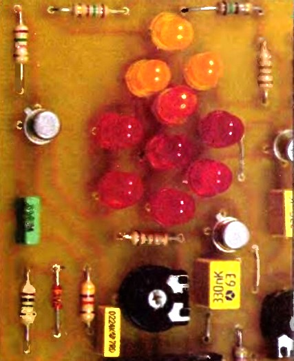
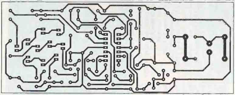
All the components are grouped on a single long board, and the trace of the tracks is shown in the PCB design below.

The LED diodes are grouped at the top of the board in the shape of a flame by mixing red, orange, and yellow components.
For capacitors C1 and C2, it is highly recommended to choose a minimum insulation voltage of 400V or preferably 630V if possible.
The chosen schematic for our power supply is indeed very economical but requires the utmost caution because one of the mains pins is directly connected to the positive pole of the power supply.
How to Setup
The adjustment for this electronic candle flame simulator circuit is straightforward: using an insulated screwdriver, after powering on, you will achieve a brief glow on one or the other of the LED groups by maneuvering the P1 adjustable resistor.
The P2, P3, and P4 adjustable resistors allow for different illuminations on the three groups of indicators for better realism. Obtaining a flickering and subtle glow of the flame will be easy to achieve.
We strongly advise you to take precautions when handling this assembly and consider the safety measures when powering it on.
Conclusion
In conclusion, we have explored the design and functionality of an electronic candle flame simulator circuit.
This circuit offers a safe and clean alternative to traditional candles, replicating the flickering and subtle glow of a real flame using red, orange, and yellow LED diodes.
The components are compactly arranged on a single board, ensuring convenience and ease of use. With the use of a white noise generator and amplification stages, the circuit produces a randomized low-voltage signal, mimicking the natural variation of a flame.
The integrated LM324 circuit and voltage comparators further enhance the realism of the LED flame, allowing for different illuminations and creating an engaging visual effect.
It is vital to note that owing to the circuit's connection to the mains power supply, suitable measures should be used when handling it.
To guarantee a secure and dependable functioning, safety precautions and a thorough comprehension of the schematic are required.
With this electronic candle flame simulator, you can enjoy the ambiance and calming effect of candlelight without the risks associated with open flames.
Whether used for decorative purposes, relaxation, or creating a cozy atmosphere, this circuit provides a long-lasting and realistic flame experience.
Embrace the charm of candlelight with the convenience and safety of electronics through this innovative electronic candle flame simulator circuit.


Need Help? Please Leave a Comment! We value your input—Kindly keep it relevant to the above topic!