It's John Ambrose Fleming (1849-1945), a British engineer, who invented the first diode in 1904, in the form of an electron tube. Later, with the development of semiconductor technology, the diode became a dipole consisting of two substrates: one, rich in free electrons, and of type N, the other deficient in electrons, and of type P.
The diode only allows current to flow in the P-N direction. The doped P part is called the anode, while the cathode corresponds to the doped N part.
General Working
When inserted into a circuit, a diode is in a blocking state if the cathode potential is higher than that of the anode.
However, if the potential is reversed, it can be observed that current only begins to flow if the potential value is greater than a threshold voltage. For typical silicon diodes, this threshold voltage is around 0.6 volts. It is 0.3 volts for germanium diodes and can reach up to 3 volts for light-emitting diodes (LEDs).
This voltage remains almost constant for all current levels crossing the junction, as long as they do not exceed the nominal value for which the diode was designed.
By hydraulic analogy as shown below , the operation of a diode can be compared to a pipeline in which a ball check valve only allows a flow of liquid in the direction where pressure pushes the ball down by compressing a spring.
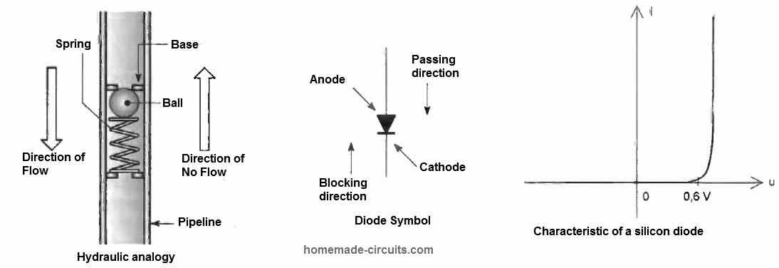
The "threshold pressure" is the pressure required to neutralize the action of the spring pushing the ball onto its seat.
Direct current behavior - Single diode
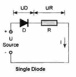
Consider a direct current source with a potential of U supplying a circuit consisting of a resistance R in series with a diode D. For a current to be established, it is necessary to satisfy the condition:
U > UD
A potential UD is measured across the diode. In the case of a silicon diode, UD = 0.6 V.
The potential difference across R is given by UR = U - 0.6 V, and the current I is determined by applying Ohm's law: I = UR / R.
The diode D dissipates power P = 0.6 x I.
If the value of I exceeds the nominal limit of the diode, the temperature of the diode increases significantly, which can lead to its destruction.
Diodes connected in series
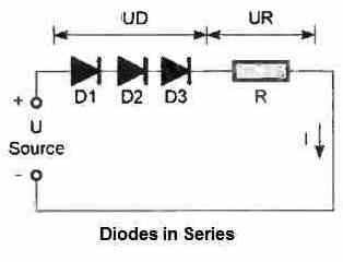
The establishment of a current is subject to the condition U > 1.8 V (since 3 silicon diodes are connected in series, each having a threshold voltage of 0.6 V). Indeed, the threshold voltages are added in this type of connection.
As explained previously, the value of the potential difference across R can be calculated by applying the relationship:
UR = U - 1.8 V
Similarly, for the current I = UR / R, and the total power P dissipated in the three diodes is 1.8 x I. If the diodes have the same characteristics, the power dissipated by each diode will be one third of the total power.
Connecting diodes in series allows for a fixed potential, which is a multiple of the threshold potential of the diodes, to be obtained. This potential can be used as a reference in certain applications where the current is variable.
Diodes connected in parallel
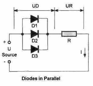
In practice, a parallel connection of diodes is not useful. Simply because, the current I will flow through the diode with the lowest threshold potential (forward voltage drop). This will result in almost no current flowing in the other parallel diodes.
This implies that one of the diodes would be conducting and allowing the entire current to flow through it, while the other diodes would remain turned OFF. It should be noted that even identical diodes have different manufacturing tolerances, so there will always be differences in the threshold potential.
Use in Alternating Current
The rectification of alternating current is a typical example of the use of diodes. Depending on the case, one or more diodes can be used.
Use of a Single Diode
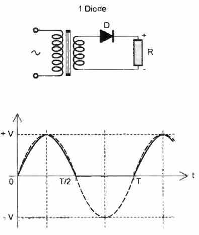
This is the simplest case. The diode only allows one alternating current cycle to pass through, so that a pulsed unidirectional current is obtained, with interruptions of equal duration to those that are active, if the diode's threshold potential is neglected.
In the case of a sinusoidal alternating current, by mathematically integrating one cycle, the calculation of the average value of the voltage generated leads to the following relationship:
Um = V/π
where, Um = Average voltage, V = Peak voltage
Note that the peak voltage is obtained from the root-mean-square value of the alternating voltage (the value given by a multimeter) using the relationship:
V = Veff√2
Ultimately, the value of the average voltage can be calculated using the relationship:
Um = 0.45 Veff
Use of Two Diodes
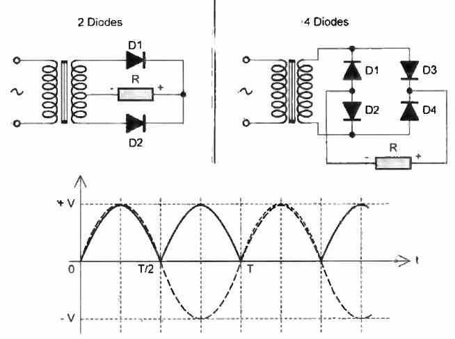
This type of rectification requires a transformer with a secondary winding that either has a center tap or two identical windings that are tied together to create a center tap. This center tap then becomes the "negative" of the rectified alternating voltage.
Compared to the single diode case, here the rectification of both alternating cycles is obtained. If Veff is the effective value of one of the two windings, the average voltage is determined by the following relationship:
Um = 0.90 Veff
Use of Four Diodes
The advantage of this configuration lies mainly in the fact that there is no longer a need for a transformer with a secondary winding that has a center tap, while still producing rectification of both alternating cycles. For a value Veff of the voltage delivered by the secondary winding, the resulting average voltage is expressed by the relationship:
Um = 0.90 Veff
The specific arrangement of the diodes constitutes a configuration called the "Graetz bridge."
Filtering
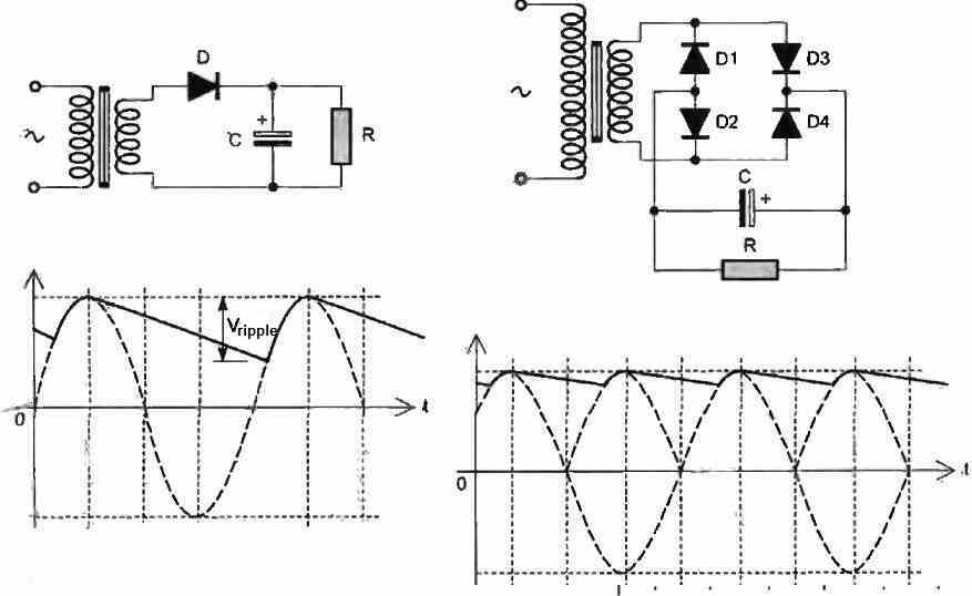
A rectified voltage, although unidirectional, is far from being continuous. A solution to this problem is filtering.
A simple way to achieve this is by placing a capacitor in parallel with the load resistance and downstream of the diode. The capacitor acts as an energy reservoir that fills the absence of potential during the dead times by returning the charge acquired during the previous half-period.
The filtering will be more effective as the value of the capacitance is made larger. The resulting signal shape is characterized by more or less pronounced ripples. In the case of rectification with a single diode, it can be shown that the ripple voltage Vripple is determined by the following relationship:
Vripple = I / C.f
where, I = Current in the load resistor R, C = Capacitance of the filtering capacitor, f = Frequency of the rectified alternating current
This smoothing of the potential can be improved by using double-alternate rectification. Typically, an active device such as a voltage regulator is placed downstream to obtain a perfectly continuous current.
Applications
Voltage Doublers
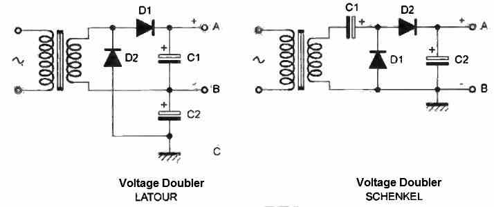
A first type of voltage doubler is the Latour doubler.
During the positive half cycle, diode D1 conducts, while D2 is blocked. Capacitor C1 charges up to the maximum voltage (peak voltage)
that is:
U = Veff√2
During the negative half cycle, the situation is reversed: D1 is blocked and D2 conducts. Therefore, capacitor C2 also charges up to the value of U.
Thus, between points A and C, a potential of 2.U is obtained. Additionally, this doubler allows for the realization of a symmetrical power supply with B as the midpoint.
There is a second type of voltage doubler: the Schenkel doubler. During the negative half cycle, diode D2 is blocked and diode D1 is conducting. This results in the charging of capacitor C1 to the peak voltage U.
During the positive half cycle, C2 charges through D2, but at a voltage of 2.U, due to the addition of the U value specific to capacitor C1. Thus, between points A and B, a doubled voltage of U is obtained.
Detection
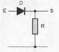
The diode only conducts when the potential is above the diode's threshold voltage.
Backup
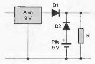
When the mains power supply fails (e.g., power outage), the battery ensures the backup of the utilization circuit through diode D2.
Clamper
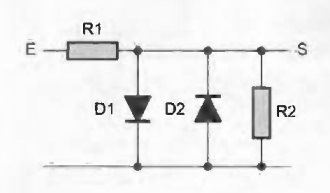
The example shown is the one used for the input of an amplifier, whose potential must always remain below 0.6 V.
If this limit value is exceeded (either positively or negatively), diode D1 or D2 clips the voltage spike at 0.6 V, which is the diode's threshold voltage.
Transistor protection
When transistor T is blocked, a self-induced reverse voltage occurs at the relay coil terminals, which is forced into the collector circuit, and can damage the transistor. Diode D is used to dissipate this reverse voltage.
Other Diodes
Schottky Diode
In this diode, the P/N junction has been replaced by a metal-semiconductor junction with low-doped N-type semiconductor. It has a much lower capacitance than traditional diodes. Moreover, its threshold voltage is only 0.25 V.
Varicap Diode
This is a diode used as a variable capacitance that is controlled by the reverse voltage applied to it. This possibility allows varying a capacitance electronically in an oscillating circuit. This is achieved without mechanically and manually acting on the variable capacitor of the diode.
Zener Diode
Used in the forward direction anode-cathode, this type of diode behaves like a normal diode, provided the reverse voltage applied to it does not exceed its characteristic voltage, known as the "zener voltage."
When subjected to a reverse voltage beyond its characteristic value, it suddenly becomes conductive (avalanche effect).
Connected in series with a resistor, the potential measured on the cathode of the Zener diode remains constant. This is why this type of diode is often found in voltage regulator circuits.


Comments
Hi Swagatam;
I think for instant 1n4001 allows the current up to 1 ampere. However, if they were used 4 pcs of them in a rectifier bridge so that means this rectifier capacity is 2 amperes or what?
My other question is that it is possible to use flyback or shotky diodes to make bridge rectifier?
Best Wishes
Hi Suat,
1 amp is the maximum current handing capacity for 1N4001—1N4007 diodes, but they can start heating up even at 400 mA.
The maximum current handling capacity of a bridge rectifier using 1N4001–1N4007 diodes will be 1 amp only, not 2 amps.
Yes, shottky diodes can be used for making bridge rectifiers.