The O.E.M. turn signal flashing units installed in automobiles have two basic functions i.e. Flasher and Lamp outage detection.
These flashers are usually built with an 8-pin IC like U2044B, U6432B etc. which are specifically made for automotive flashers.
Designed and Written By Abu-Hafss
Circuit Operation
These flashers normally oscillate at about 1.4Hz. When a lamp goes bad, the oscillation is doubled.
The flasher’s faster clicking sound and the dashboard indicator’s faster flashing attracts the driver’s attention that one of the bulbs has gone out.
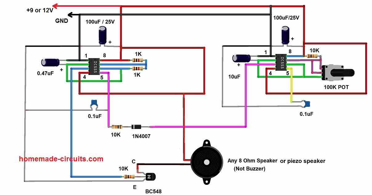
Here, I have explained a flasher circuit which performs similarly but uses a 555 IC and two comparators.
The circuit consists of two parts – the flashing unit and the lamp outage detection module. The flashing unit is built around 555 timer configured as an astable multivibrator.
The resistors R12/R13 and capacitors C3/C4 sets the required frequency. Note that C3 is connected in parallel to C4 thru an NPN transistor, acting as a switch.
When there is positive voltage at the base of the transistor, it conducts and connects C3 to ground. C3 & C4 in parallel makes the capacitance value double i.e. 220nF + 220nF = 440nF. This capacitance value together with R12 and R13 result in frequency of about 1.4Hz.
In the Lamp outage detection module, a shunt resistor (a thick wire) with a calculated minor resistance (30mΩ) is the key to detect the lamp outage.
The voltage to lamps is fed thru this shunt. Hence, the shunt is connected in series to the network of the bulbs which are connected in parallel.
The inverting input (-input) of the comparator U1 is also connected to the shunt. The non-inverting input (+input) is connected to a potential divider providing a reference voltage of 11.90V.
NORMAL OPERATION:
-input = Square wave between 11.89V – 12.0V
+input = 11.9V (reference voltage)
The comparator U1 compares the two voltages and the output is a square wave between 0-12V. This output is rectified thru diode D1 and filtered thru capacitor C1.
Now, we have a triangular wave form which is fed into another comparator U2.
+input = Triangular wave between 7V – 8V -input = 1V (reference voltage)
The comparator U2 compares them; the output is constant 12V which goes to the base of the NPN transistor.
This switches on the NPN and hence C3 is connected to ground. In result, the 555 timer oscillates at about 1.4Hz.
The output of 555 is connected to relay RLY1 which relays 12V direct from the battery (thru shunt) to the lamps.
OPERATION WITH A DEFECTIVE LAMP:
When a bulb is defective, there is an increase in the resistance of the bulb network hence the voltage drop across the shunt is changed. So, in this case we would have:
-input = Sq. wave between 11.95V – 12V
+input = 11.90V (reference voltage)
The comparator U1 compares them and the output is almost zero volts. After the diode and the filter network, we finally have a few millivolts at the +input of U2 which is compared with the reference voltage, 1V.
This results in low output of U2 which ultimately switches off the NPN and hence C3 is disconnected from the ground.
Now, the timing network of 555 has only C4 to work with, therefore the frequency of the oscillation is doubled. This causes the remaining bulbs to flash at doubled rate.
Circuit Diagram


Comments
I put LED tail lights on my truck. Doing so required me to swap out the wiring harness for each light. After the install, I noticed the bulb outage detection wired were not connected to anything, as in the factory harness coming from the BCM has 5 wires and the one I purchased to make my new tail light wires work has 4.
The bulb outage detection wire has a reading of 11.9V and I’ m getting hyperflash on both sides. How can I wire the bulb outage detection wire (or what can I connect it to) to trick it into thinking there isn’t a bulb out?
Thanks!!
The outage detection wires probably requires a load to satisfy the detection circuit. You might have to connect an actual light bulb between the detection wire and ground to satisfy the load conditions. A resistor might not work since it might get too hot.