• Skip to main content
  • Skip to primary sidebar

Homemade Circuit Projects

Need circuit help? Post them in the comments! I've answered over 50,000!

Blog | Categories | About | Contact | Calculators-online
You are here: Home / Datasheets and Components / BT169 SCR Datasheet [200 V, 0.5 A SCR]

BT169 SCR Datasheet [200 V, 0.5 A SCR]

Last Updated on March 25, 2023 by Swagatam Leave a Comment

The BT169 is a thyristor or SCR (Silicon Controlled Rectifier) that is commonly used for switching applications in low-power electronic circuits. It can be used for small signal, low current applications. Its size is very small just like a BJT. Here are the full technical specifications of the BT169:

Table of Contents
  • Electrical Specifications
  • Pinout:
  • Applications
  • Making a "Door was Opened" Indicator using BT169 SCR

Electrical Specifications

  • Maximum repetitive peak off-state voltage (VDRM): 400V
  • Maximum RMS voltage (VRMS): 240V
  • Maximum DC blocking voltage (VDC): 400V
  • Maximum average forward current (IF(AV)): 0.5A
  • Peak non-repetitive surge current (ITSM): 2.5A
  • Peak repetitive forward and reverse blocking current (IDRM): 5μA
  • Gate trigger voltage (VGT): 0.8V
  • Gate trigger current (IGT): 0.2mA
  • Holding current (IH): 0.1mA
  • Maximum junction temperature (Tj): 125°C
  • Maximum storage temperature (Tstg): -40 to 150°C
  • Package type: TO-92
  • Maximum forward voltage drop (VF): 1.5V
  • Maximum reverse leakage current (IR): 10μA
  • Gate trigger voltage range: 0.8V to 2.5V
  • Maximum gate voltage (VGTM): 5V
  • Maximum on-state voltage (VTM): 1.7V
  • Maximum turn-off time (tq): 20μs
  • Maximum gate non-trigger voltage (VG): 0.5V
  • Maximum gate non-trigger current (IG): 0.05μA
  • Maximum reverse recovery time (trr): N/A (not applicable as this is an SCR)
  • Thermal resistance, junction to ambient (RthJA): 200°C/W

Pinout:

The BT169 SCR comes in a TO-92 package with three leads. The pinout is as follows:
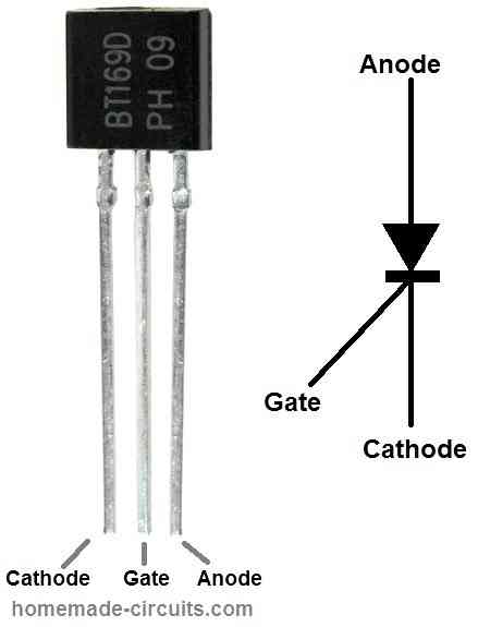
BT169 pinout configuration
  • Cathode (K)
  • Gate (G)
  • Anode (A)

Applications

The BT169 SCR can be used in a variety of low-power electronic circuits for switching and control applications. Some common applications of the BT169 include:

  1. Lamp dimming control: The BT169 can be used in lamp dimmer circuits to control the brightness of incandescent bulbs.
  2. Motor control: The BT169 can be used to switch on and off small DC motors in electronic control circuits.
  3. Power supply circuits: The BT169 can be used in voltage regulator circuits to control the output voltage.
  4. Thyristor control circuits: The BT169 can be used in combination with other thyristors to control the flow of current in power electronics applications.
  5. Solenoid and relay control: The BT169 can be used to control the operation of solenoids and relays in electronic circuits.

Making a "Door was Opened" Indicator using BT169 SCR

A simple magnetic "door was opened" indicator circuit can be made using a BT169 SCR, a reed switch, a magnet and a few resistors.

door open indicator circuit

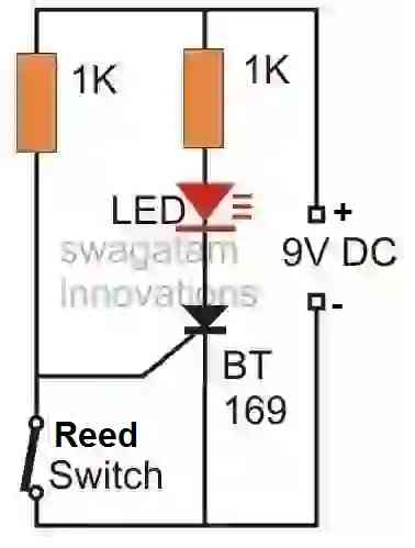
Connect the reed switch between the gate and cathode of the reed relay.

Connect a resistor between gate and the positive supply of the circuit.

Connect an LED with a series 1K resistor between the anode and the positive supply of the circuit.

Connect a 9V battery to power the circuit.

Attach the circuit at the edge of the door, and attach a magnet at the frame of the door such that the reed switch and the magnet line up close to each other.

Once the circuit is installed the magnet will keep the reed switch closed, which will ground the SCR gate keeping it switched OFF.

Press the reset button to ensure that the LED is switched OFF while the door is in the closed condition.

This reset button is not shown in the diagram. It is a push-to-ON switch which can be attached across the anode and cathode terminals of the SCR.

Now, as soon as somebody opens the door, the reed switch opens removing the ground supply from the SCR gate.

This causes the voltage to flow to the gate and trigger it ON.

The SCR latches ON switching ON the LED.

Due to its latching property the SCR remains latched ON keeping the LED illuminated even if the door is closed back.

You'll also like:

  • 1.  2N3904 Datasheet [40V, 200 mA NPN Transistor]
  • 2.  Compact 3-Phase IGBT Driver IC STGIPN3H60 – Datasheet, Pinout
  • 3.  L293 Quad Half-H Driver IC Pinout, Datasheet, Application Circuit
  • 4.  IC 4026 Datasheet, Pinout Working, Application
  • 5.  12V 5 Amp Fixed Voltage Regulator IC 78H12A Datasheet
  • 6.  High Current Zener Diode Datasheet, Application Circuit

Filed Under: Datasheets and Components Tagged With: 200, BT169, Datasheet, SCR

About Swagatam

I am an electronics engineer and doing practical hands-on work from more than 15 years now. Building real circuits, testing them and also making PCB layouts by myself. I really love doing all these things like inventing something new, designing electronics and also helping other people like hobby guys who want to make their own cool circuits at home.

And that is the main reason why I started this website homemade-circuits.com, to share different types of circuit ideas..

If you are having any kind of doubt or question related to circuits then just write down your question in the comment box below, I am like always checking, so I guarantee I will reply you for sure!

Previous Post: « Child Crying Monitor Circuit using Power Line Communication
Next Post: Windshield Washer Fluid Indicator Circuit »

Reader Interactions

Need Help? Please Leave a Comment! We value your input—Kindly keep it relevant to the above topic! Cancel reply

Your email address will not be published. Required fields are marked *

Primary Sidebar

circuit simulator image


Categories

  • Arduino Projects (89)
  • Audio and Amplifier Projects (132)
  • Automation Projects (17)
  • Automobile Electronics (101)
  • Battery Charger Circuits (83)
  • Datasheets and Components (104)
  • Electronics Theory (143)
  • Free Energy (37)
  • Games and Sports Projects (11)
  • Grid and 3-Phase (19)
  • Health related Projects (25)
  • Home Electrical Circuits (12)
  • Indicator Circuits (14)
  • Inverter Circuits (88)
  • Lamps and Lights (142)
  • Meters and Testers (69)
  • Mini Projects (46)
  • Motor Controller (64)
  • Oscillator Circuits (27)
  • Pets and Pests (15)
  • Power Supply Circuits (108)
  • Remote Control Circuits (50)
  • Security and Alarm (64)
  • Sensors and Detectors (102)
  • Solar Controller Circuits (59)
  • Temperature Controllers (42)
  • Timer and Delay Relay (49)
  • Transmitter Circuits (29)
  • Voltage Control and Protection (40)
  • Water Controller (36)


Other Links

  • Privacy Policy
  • Cookie Policy
  • Disclaimer
  • Copyright
  • Videos
  • Sitemap

People also Search

555 Circuits | 741 Circuits | LM324 Circuits | LM338 Circuits | 4017 Circuits | Ultrasonic Projects | SMPS Projects | Christmas Projects | MOSFETs | Radio Circuits | Laser Circuits | PIR Projects |


Social Profiles

  • Twitter
  • YouTube
  • Instagram
  • Pinterest
  • My Facebook-Page
  • Quora
  • Stack Exchange
  • Linkedin


  • Recent Comments

    • Swagatam on Make this DC CDI Circuit for Motorcycles
    • Tony on Make this DC CDI Circuit for Motorcycles
    • Swagatam on How to Make Dog Barking Preventer Circuit using High Frequency Deterrence
    • Swagatam on How an Inverter Functions, How to Repair Inverters – General Tips
    • Dady on How an Inverter Functions, How to Repair Inverters – General Tips

    © 2025 · Swagatam Innovations