This BQ24295 IC is like a super smart charger chip. This one is not just for charging battery, but also doing many other jobs like boost converter, USB detection, power path control, and even OTG (host power supply). So we can say that this is a full battery charging and power management IC.
Let us try to understand everything about it slowly and deeply.
What BQ24295 Actually Does
- This BQ24295 chip is not just a battery charger but inside it has full smart circuit which can charge, boost, detect USB and even decide how power should flow, like battery to system or USB to battery or USB to system.
- This IC works perfectly with single 3.7V Li-Ion or Li-Po cells and can be charged from USB port or wall adapter or any 5V–9V input.
- It also has logic to decide which source to give priority. So when USB is connected then it gives power from USB and saves battery. But when USB is not there then it gives power from battery to output system.
- One more awesome thing it does is OTG. That means it can take battery power and boost it to give 5V at USB port. So we can use this to make DIY power bank also.
Full Internal Block Idea
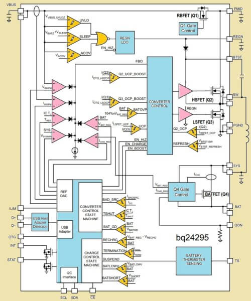
- Inside this IC there is a buck converter circuit which takes higher voltage from USB or adapter and steps it down properly to charge the battery without heating too much.
- There is one intelligent power path controller inside which decides where to send the current, whether to battery or to system output or both together.
- It has internal logic to monitor battery voltage and current levels continuously. It knows when battery is deeply discharged or when it is full and adjusts charging accordingly.
- It also has an internal boost converter circuit. This one takes 3.7V from battery and lifts it up to 5V, so we can give it out through VBUS in OTG mode.
- It comes with a full register table that works with I2C. So we can connect Arduino or ESP32 and read or control all settings, charging status, etc.
- Finally it has very strong protection systems inside, like it checks for over voltage, over current, high temperature, wrong connection, battery removal and all such faults.
Basic Features Overview
| Feature | Details |
|---|---|
| Battery Support | 1-cell Li-Ion or Li-Polymer |
| Input Voltage | 3.9V to 17V (20V max abs) |
| Charging Current | Up to 4A |
| Input Detection | USB SDP/CDP/DCP or adapter |
| Communication | I2C interface |
| Output Boost | 5V OTG boost from battery |
| Safety | OVP, UVLO, Thermal, Battery OTP |
| System Output | 4.36V max (for load power) |
| Charging Algorithm | CC-CV with termination |
| Package | 24-pin QFN |
Pin Configuration (Important Pins)
| Pin Name | Function |
|---|---|
| PMID | Main output pin for system load |
| VBUS | Input for USB or adapter |
| BAT | Battery connection pin |
| OTG | Boost enable (active high) |
| SDA/SCL | I2C communication lines |
| STAT | Status pin (charging/done/fault) |
| CE | Charge enable (low = ON, high = OFF) |
| TS | Battery thermistor (NTC) input |
| PG | Power good (low = OK) |
| REGN | Internal 3.3V LDO output |
| ISET | Sets charging current using resistor |
| ILIM | Sets input current limit |
| SYS | Output to system load |
| GND | Ground |
How Charging Actually Works?
So this IC follows 3-stage charging algorithm:
- Pre-Charge Stage: If battery voltage is very low (<3V) then it first gives small current (like 10%) to bring battery safely up.
- Fast Charge (CC) Stage: Then once battery reaches 3V+ then it starts full constant current charging, as set by ISET resistor.
- Voltage Regulation (CV) Stage: After battery reaches around 4.2V then it slowly reduces current and maintains voltage. When current drops below ~10% of ISET value then it stops (terminates) charging.
This way battery stays safe and does not get overcharged.
Charging Current and Limit Settings
| Parameter | How to Set |
|---|---|
| Charge Current | Set by resistor at ISET pin: ICHG = K_ICHG / R_ISET (K = 890 by default) |
| Input Current Limit | Set by resistor at ILIM pin: ILIM = K_ILIM / R_ILIM (K = 1.44k) |
| Termination Current | ~10% of fast charge current (auto) |
| Top-off Voltage | Usually 4.2V (adjustable via I2C) |
So for example if we use 890 ohms at ISET, then:ICHG = 890 / 890 = 1A charging current
Charging Current and Limit Settings
- The charging current is decided by connecting a resistor at ISET pin. This resistor tells the IC how much maximum current to push into the battery. It uses formula like ICHG = 890 / R.
- The input current limit is also set using a resistor at ILIM pin. This resistor controls how much current the IC will take from USB or adapter. So this protects the USB port from overload.
- Termination current is automatically calculated by the IC. When battery is almost full and the charging current drops below 10% of the set value, it automatically stops charging.
- The top voltage at which charging is stopped is around 4.2V, and this value also can be adjusted using I2C if we want different battery chemistry.
OTG Boost Mode
- When we want to use battery to give 5V output to USB port then we can activate OTG mode by pulling OTG pin high or by sending command through I2C.
- After enabling OTG, then IC takes 3.7V from the battery and boosts it to make 5V output and this 5V comes out at the VBUS pin.
- The IC can give around 1.3A in this OTG boost mode which is enough for small gadgets or phone charging also.
- This function is very useful when we are designing our own DIY power banks or battery-powered USB output systems.
Status Indications
- The STAT pin becomes LOW when charging is going on. So we can connect an LED to it to show “charging in progress.”
- When charging is completed, then STAT pin becomes HIGH. So we can make LED turn OFF or show “charging done.”
- If there is any fault, like temperature problem or over current, then this STAT pin will start blinking continuously. That helps us knowing something is wrong.
Protections
- If someone connects very high voltage like more than 20V to input, then IC will detect it and stop working to protect itself.
- If the battery becomes too hot or too cold, then IC will read the temperature using NTC thermistor connected at TS pin and stop the charging to prevent battery damage.
- If battery output becomes shorted or connected wrongly, then IC will shut off output to prevent any burning.
- If the IC itself becomes hot due to continuous working or poor heat dissipation then it will enter thermal shutdown and stop charging until it cools down.
- If battery is not connected properly or loose contact happens, then IC will detect it and stop charging until battery is reconnected.
I2C Control and Readings
- The IC allows us to control almost every function through I2C interface which makes it very flexible to work with microcontrollers like Arduino, ESP32, STM32 etc.
- We can read actual voltage, charging current, battery temperature and other data by reading I2C registers from the IC.
- We can also send commands to start or stop charging, change charging current or voltage and even turn on OTG mode.
- We can read fault registers to know what kind of problem happened, like over-voltage or battery not connected.
Basic Application Circuit
- We just need to connect VBUS pin of the IC to USB port or 5V adapter and connect BAT pin to the positive of Li-Ion battery.
- Then SYS pin will give output power to our load, like Arduino or WiFi module or sensor.
- SDA and SCL should be connected to I2C pins of the microcontroller with 10k pull-up resistors to 3.3V.
- Add a 10k NTC thermistor between TS and GND or if not used then fix the voltage divider to show normal temperature range to the IC.
- Rest of the things are managed by the IC automatically, like detection, switching, protection, charging, boost etc.
Full Explanation of BQ24295 Application Circuit

VBUS Pin (Top Left)
- This is the main input for 5V from USB source like SDP (Standard Downstream Port) or DCP (Dedicated Charging Port).
- It goes through C2 (1 µF) capacitor to ground, this helps to filter noise and stabilize the input.
- This voltage also feeds into PMID through a MOSFET switch inside the IC.
PMID Pin
- This is a power rail generated by internal FET between VBUS and PMID.
- Acts as main power source for the system during USB charging.
- C1 (20 µF min) capacitor stabilizes this rail.
- R6 (10k) is just a weak pull-up from SYS to keep things active (no harm, just biasing help).
ILIM Pin
- We connect a resistor R1 (317 ohms) from ILIM to ground. This sets the input current limit from USB port.
Formula is:
I_ILIM = K_ILIM / R_ILIM
Where K_ILIM = 1320 (typical value)
R_ILIM = 317 ohm
So, I_ILIM ≈ 1320 / 317 ≈ 4.16 A (but IC clamps to 1.5A max)
D+ / D- (USB Detection Pins)
- These go to USB lines (data lines), used for USB protocol detection (like SDP, CDP, DCP types).
- Helps BQ24295 identify if source is standard USB or high current charger.
SYS Pin
- This is system output rail, powers the system when battery or USB is available.
- SYS is connected to load (like LEDs, microcontroller etc).
- R2 (2.2k) and LED from SYS to STAT shows charging status (when STAT is pulled LOW).
STAT Pin
- Open-drain output. It connects to LED to indicate charging status:
- ON = Charging
- OFF = Done or No battery
- Blinking = Fault
I2C Pins: SDA, SCL
- Used to talk with Arduino or microcontroller via I2C protocol.
- You can configure charge current, battery voltage, status, etc through these lines.
- Pull-ups R3, R4, R5 (all 10k) to 3.3V required.
INT Pin
- Interrupt output pin. Goes LOW when charge status or faults change.
- Your MCU can check what’s going on.
CE Pin (Charge Enable)
- If LOW = Charging allowed
- If HIGH = Charging disabled
- We usually control this with Arduino or pull LOW directly to keep it enabled.
SW / BTST / REGN / PGND Section (Right Side Buck Converter)
- SW is the switching pin connected to an inductor L1 (2.2 µH).
- C3 (47nF) and C4 (4.7 µF) are snubber and bypass caps.
- BTST is boot strap cap pin – connected to C3.
- REGN is internal LDO (6V) output used to drive switching FETs.
- All these work together like buck converter to step-down 5V and charge battery efficiently.
BAT Pin (Battery Terminal)
- This goes to positive terminal of Li-ion or Li-Po battery.
- C5 (10 µF) for stability.
- Optional FET can isolate battery in some cases (optional).
QON Pin
- Used for system wake-up or battery FET control.
- Not always used in simple setup so most of time left unconnected or tied to SYS.
TS Pin (Temperature Sense)
- Connects to NTC thermistor (10k at 25°C).
- Ensures battery charges only when it is in safe temperature range (0°C to 45°C).
- In this circuit:
- RT1 = 5.25k
- RT2 = 31.23k
- RTH = 10k NTC
- These form a resistor divider for temperature window.
Thermal Pad
- Must be soldered to PCB ground plane properly to dissipate heat.
Summary of Capacitors and Inductors
| Component | Value | Purpose |
|---|---|---|
| C1 | 20 µF | Output bulk filter on PMID |
| C2 | 1 µF | VBUS input decoupling |
| C3 | 47 nF | Bootstrap capacitor (BTST) |
| C4 | 4.7 µF | REGN decoupling |
| C5 | 10 µF | Battery output filter |
| C6, C7 | 10 µF | SYS output stability |
| L1 | 2.2 µH | Buck inductor for charger loop |
Important Calculations
ILIM Resistor Formula:
R_ILIM = K_ILIM / I_LIMIT
Where K_ILIM ≈ 1320
Example: I_LIMIT = 1.5 A
R_ILIM = 1320 / 1.5 ≈ 880 ohms
Thermistor Divider Thresholds:
For 10k NTC and default charge range (0°C to 45°C):
- Set using:
V_TS = V_REGN * [RTH / (RT1 + RTH + RT2)]So design RT1, RT2 for proper window.
What You Can Do with This BQ24295 Battery Charger Circuit
- Charge 1-cell Li-Ion/LiPo battery from USB or adapter.
- Control & monitor charging using Arduino or MCU via I2C.
- Get charge status, current, voltage, faults.
- Fully automatic + programmable charge system for portable devices.
Now, in the next section I am giving you the full Arduino code for I2C communication with BQ24295, along with the complete connection details and how the wiring is supposed to go.
Full Circuit Connections for BQ24295 with Arduino
Here is how we connect everything step-by-step:
| BQ24295 Pin | Connects To | Notes |
|---|---|---|
| VBUS | +5V from USB / Adapter | Power input for charging |
| GND | Arduino GND & Battery GND | Common ground |
| BAT | Positive of 3.7V Li-ion cell | Direct battery terminal |
| SYS | Output to load (Arduino Vin) | Can be used to power Arduino if battery available |
| SCL | Arduino A5 (I2C Clock) | Add 4.7k or 10k pull-up to 3.3V |
| SDA | Arduino A4 (I2C Data) | Add 4.7k or 10k pull-up to 3.3V |
| TS | NTC thermistor or fixed divider | Optional, can use voltage divider for fake NTC |
| STAT | LED (with 1k) or Arduino input pin | Shows charge/fault status |
| OTG | Optional switch or Arduino pin | To enable OTG 5V boost mode |
| ILIM, ISET | Resistors to GND as per charging current requirement | ICHG = 890/R (R in kΩ) |
| CE | Connect to GND to enable charging | Or control using Arduino pin (LOW = enable) |
Important: This IC is 3.3V logic so if your Arduino is UNO (5V), then use level shifter or resistive divider for SDA/SCL.
Arduino Code for Reading BQ24295 Registers via I2C
#include <Wire.h>

// I2C Address of BQ24295
#define BQ24295_ADDR 0x6B  // Default I2C address

// Register map (only few important ones shown)
#define REG_STATUS     0x0B
#define REG_FAULT      0x0C
#define REG_INPUT_SRC  0x00
#define REG_POWER_ON   0x01
#define REG_CHG_CTRL_0 0x04

void setup() {
  Serial.begin(9600);
  Wire.begin();  // Join I2C bus

  delay(1000);
  Serial.println("Starting BQ24295 Monitor...");

  // Optional: Configure input current limit
  writeRegister(REG_INPUT_SRC, 0b00010000); // Set 500mA input limit

  // Optional: Enable charging manually (if CE is tied to logic)
  writeRegister(REG_POWER_ON, 0b00011011);  // Default safe config
}

void loop() {
  // Read and display charger status
  byte status = readRegister(REG_STATUS);
  byte fault = readRegister(REG_FAULT);

  Serial.print("Charger Status: ");
  decodeStatus(status);

  Serial.print("Fault: ");
  decodeFault(fault);

  delay(2000);
}

byte readRegister(byte reg) {
  Wire.beginTransmission(BQ24295_ADDR);
  Wire.write(reg);
  Wire.endTransmission(false);  // Restart for reading
  Wire.requestFrom(BQ24295_ADDR, 1);

  if (Wire.available()) {
    return Wire.read();
  } else {
    return 0xFF;
  }
}

void writeRegister(byte reg, byte val) {
  Wire.beginTransmission(BQ24295_ADDR);
  Wire.write(reg);
  Wire.write(val);
  Wire.endTransmission();
}

void decodeStatus(byte data) {
  byte chg_stat = (data >> 4) & 0x03;

  switch (chg_stat) {
    case 0: Serial.println("Not Charging"); break;
    case 1: Serial.println("Pre-Charging"); break;
    case 2: Serial.println("Fast Charging"); break;
    case 3: Serial.println("Charge Terminated"); break;
  }
}

void decodeFault(byte data) {
  byte fault = data & 0x07;

  switch (fault) {
    case 0: Serial.println("Normal"); break;
    case 1: Serial.println("Input Fault"); break;
    case 2: Serial.println("Thermal Fault"); break;
    case 3: Serial.println("Battery Fault"); break;
    default: Serial.println("Unknown Fault");
  }
}
Resistor Selection (for ILIM and ISET)
Use following values for current setup:
| Resistor | Pin | Formula | Example |
|---|---|---|---|
| R_ILIM | ILIM | I_ILIM = 1360 / R_ILIM (kΩ) | For 1A, R = 1.36kΩ |
| R_ISET | ISET | I_CHG = 890 / R_ISET (kΩ) | For 1A, R = 0.89kΩ |
Optional Additions
- Use a 10k NTC thermistor at TS pin to enable temperature monitoring.
- Add LED at STAT pin with 1k resistor to indicate charge status (ON = Charging, OFF = Done, Blink = Fault).
- You can connect OTG pin to a GPIO pin and pull it HIGH in code to enable OTG (5V boost).
Important Formulas for Resistor Selection
Charging Current (I_CHG):
I_CHG = 890 / R_ISET (R in k-ohms, I in Amps)For example:
- If you want 1A charging, then R_ISET = 890 / 1 = 0.89k = 890 ohms
Input Current Limit (I_INLIM):
I_INLIM = 1360 / R_ILIM (R in k-ohms)For example:
- If you want 1.5A input limit then R_ILIM = 1360 / 1.5 = 906 ohms
Summary of What All It Can Do
- So this IC can easily charge single 3.7V Li-ion or Li-Po battery using 3-stage method, like first it gives low current if battery is dead, then fast charge then finally stops when full.
- It can take USB or adapter power, even auto switch between them.
- It can also give back 5V boost from battery when needed through OTG pin.
- It can talk to Arduino using I2C protocol and send data about battery, charging, fault etc.
- You can set how much current it will give to battery using one resistor.
- You can also set how much input current it will take using another resistor.
- It gives you ready-made status pin output or if you want you can read status digitally from Arduino.
- It can sense battery temperature using thermistor so it will stop charging if battery becomes hot.
- It is very small but very powerful and all features built-in.
Source: Datasheet

Need Help? Please Leave a Comment! We value your input—Kindly keep it relevant to the above topic!