• Skip to main content
  • Skip to primary sidebar

Homemade Circuit Projects

Need circuit help? Post them in the comments! I've answered over 50,000!

Blog | Categories | About | Contact | Calculators-online
You are here: Home / Indicator Circuits / Automatic Bathroom/Toilet Engage Indicator Circuit

Automatic Bathroom/Toilet Engage Indicator Circuit

Last Updated on January 3, 2024 by Swagatam 8 Comments

In this post I have explained a very simple automatic bathroom/Toilet Engage indicator circuit which can be installed with any relevant door bolt for implementing the actions. The idea was created and submitted by Mr. Sandipan.

Table of Contents
  • The Design
  • Circuit Diagram

The Design

I have one more idea that need your help. I would like to implement is at my home ( just a simple useful fun ).

Here is my idea :

Automatic Bathroom/Toilet Engage indicator :

Requirements :

1. If a bathroom/toilet is engaged/ locked from inside ( in use ), a LED indicator ( Placed outside) should glow.

2. If the bathroom/toilet is locked from outside ( Not in use ), the indicator should not glow.

3. The bathroom/Toilet can be locked from inside using one Sliding door bolt or simple door bolt or both.

Based on the above requirement, I designed a very simple Circuit using one LED, 2 AA battery and use door locks as switch. Here is the circuit diagram

Circuit Diagram

​ IMG 1200 2

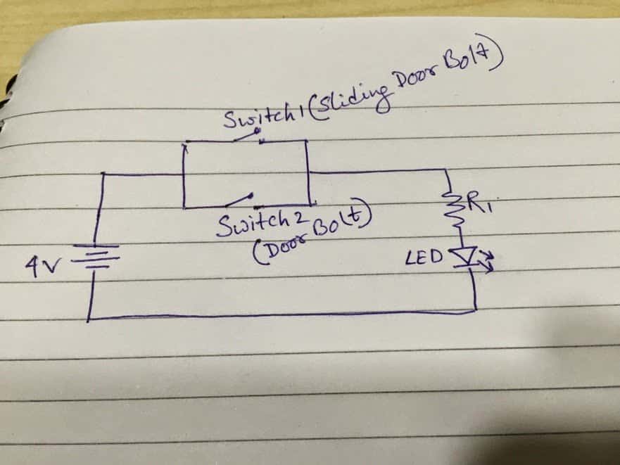
So, if any bolt or both bolt are used from inside, it complete the circuit and LED will glow.


The problem is, a lot of wiring is visible in back side of the door. I have tested this circuit using breadboard but not with Bathroom/Toilet door 🙁 .Could you please suggest any other sensor based idea/circuit ?

Thanks

Sandipan

You'll also like:

  • 1.  Simple Water Level Indicator Circuits (with Images)
  • 2.  Simple LED Music Level Indicator Circuit
  • 3.  Up/Down LED Indicator using LM3915
  • 4.  5 Useful Power Failure Indicator Circuits Explained
  • 5.  Car Speed Limit Warning Indicator Circuit
  • 6.  Make a Simplest Temperature Indicator Circuit

Filed Under: Indicator Circuits Tagged With: Automatic, Bathroom, Engage, Indicator, Toilet

About Swagatam

I am an electronics engineer and doing practical hands-on work from more than 15 years now. Building real circuits, testing them and also making PCB layouts by myself. I really love doing all these things like inventing something new, designing electronics and also helping other people like hobby guys who want to make their own cool circuits at home.

And that is the main reason why I started this website homemade-circuits.com, to share different types of circuit ideas..

If you are having any kind of doubt or question related to circuits then just write down your question in the comment box below, I am like always checking, so I guarantee I will reply you for sure!

Previous Post: « How Thyristors (SCR) Work – Tutorial
Next Post: Automatic Sliding Gate Controller Circuit »

Reader Interactions

Comments

  1. Kuldeep says

    February 5, 2022 at 6:23 pm

    Can you pls make circuit diagram for washroom occupancy indicator using reed switch. ????

    Reply
    • Swagatam says

      February 5, 2022 at 8:24 pm

      Can you briefly explain how the reed switch should sense the occupancy?

      Reply
  2. Qul 's says

    July 19, 2016 at 2:36 pm

    Sir, sorry for disturbing you. Im afiqul. Im student in UITM melaka. Can you give any schematic diagram related with toilet autolock system? I must find that schematic in this week. So i need your help sir. Thats all. Thank you sir

    Reply
    • Swagatam says

      July 20, 2016 at 3:10 am

      Hi Afiqul, please provide some more information regarding the functioning details of the lock, so that I can get a better idea

      Reply
  3. Salman Ali says

    July 6, 2015 at 2:35 pm

    I built a power bank using 6V,4.5Ah battery.

    When i Connect a cellphone for charging My phone shows that it is charging but phones battery level is not increasing instead if i run some online games while charging with it phones battery level is decreasing.

    I used 7805 IC and Two capasitor to establish a 5Volt,1A current.

    When I measure output voltage and current it is fine….but when i measure it while charging a mobile phone it shows output voltage 4.1V

    what should i fix now

    Sorry for grammatical mistake.

    Reply
    • Swagatam says

      July 7, 2015 at 4:35 am

      The 7805 IC circuit may not be required, just connect the battery output with the phone through a 1N5408 diode….

      you should not use the phone while it's being charged because the charging rate is always slower than the consumption rate, and therefore it could prevent the phone from getting charged properly.

      and make sure your 6V battery is fully charged while implementing the above

      Reply
    • Kesava Raj says

      January 8, 2017 at 9:50 am

      6v battey fully charged means the o/p value maximum 6.50v….

      While using diode ..the o/p will be above 6v.only,, diode will block ampere and little bit voltage drop… …
      Exact 5v shall i use resistor….or any other idea sir…

      For 6v 4.5Ah battery..
      For using travelling purpose sir..

      My mobile charger output 5v,1.5Ampere…

      Guide me sir….

      Reply
    • Swagatam says

      January 8, 2017 at 3:13 pm

      yes you can use a resistor, if the diode doesn't work….5V is not critical for phone charging…6V can be also used.

      Reply

Need Help? Please Leave a Comment! We value your input—Kindly keep it relevant to the above topic! Cancel reply

Your email address will not be published. Required fields are marked *

Primary Sidebar


Subscribe to New Posts

Categories

  • Arduino Projects (88)
  • Audio and Amplifier Projects (132)
  • Automation Projects (17)
  • Automobile Electronics (101)
  • Battery Charger Circuits (83)
  • Datasheets and Components (104)
  • Electronics Theory (143)
  • Free Energy (37)
  • Games and Sports Projects (11)
  • Grid and 3-Phase (19)
  • Health related Projects (25)
  • Home Electrical Circuits (12)
  • Indicator Circuits (14)
  • Inverter Circuits (88)
  • Lamps and Lights (142)
  • Meters and Testers (69)
  • Mini Projects (46)
  • Motor Controller (64)
  • Oscillator Circuits (27)
  • Pets and Pests (15)
  • Power Supply Circuits (108)
  • Remote Control Circuits (50)
  • Security and Alarm (64)
  • Sensors and Detectors (101)
  • Solar Controller Circuits (59)
  • Temperature Controllers (42)
  • Timer and Delay Relay (49)
  • Transmitter Circuits (29)
  • Voltage Control and Protection (38)
  • Water Controller (36)

Tags

Alarm Amplifier Application Arduino Automatic Battery Charger Circuits Control Controlled Controller Current Datasheet DC Detector Digital Driver Electronic Explained Explored Generator High Indicator Inverter Lamp LED Light Meter Motor Pinout Power Regulator Remote Sensor Simple Single Solar Supply Switch Timer Transistor Voltage Water Watt Working


Other Links

  • Privacy Policy
  • Cookie Policy
  • Disclaimer
  • Copyright
  • Videos
  • Sitemap


People also Search

555 Circuits | 741 Circuits | LM324 Circuits | LM338 Circuits | 4017 Circuits | Ultrasonic Projects | SMPS Projects | Christmas Projects | MOSFETs | Radio Circuits | Laser Circuits | PIR Projects |

Social Profiles

  • Twitter
  • YouTube
  • Instagram
  • Pinterest
  • My Facebook-Page
  • Quora
  • Stack Exchange
  • Linkedin


  • Recent Comments

    • Swagatam on Free Energy from Induction Cooktop
    • Swagatam on 7 Modified Sine Wave Inverter Circuits Explored – 100W to 3kVA
    • Victor on 7 Modified Sine Wave Inverter Circuits Explored – 100W to 3kVA
    • Stoyan on Free Energy from Induction Cooktop
    • Swagatam on Free Energy from Induction Cooktop

    © 2025 · Swagatam Innovations