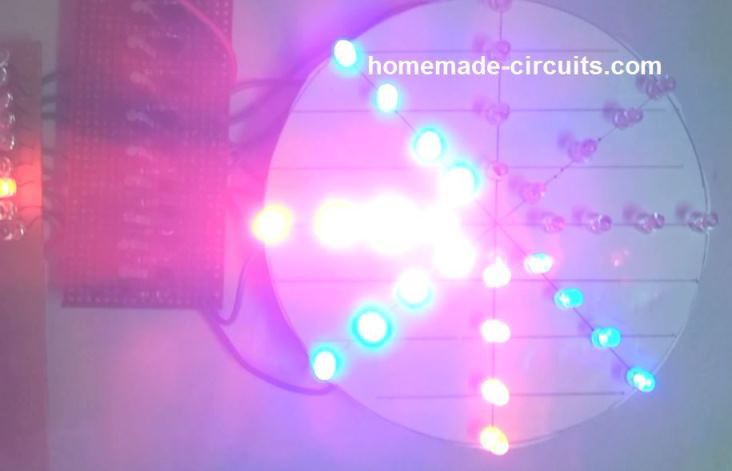
LED Chakra is an ornamental lighting system which depicts or imitates a rotating wheel like appearance, by means of sequentially shifting Illuminated LED arrays.
Indian subcontinent is a land of festivals and celebrations which mostly start from the month of August and continues until the New Year. All these festivals have one fundamental thing in common, and that is dazzling colorful lights, flashing and running with all sorts of patterns and sequences. Most of these lights are in the form of LED lights since LEDs are the most efficient in terms of brightness and cost.
In this article I will elucidate one such interesting LED ornamental project, which will imitate a rotating illuminated chakra light. These can be commonly seen behind the crown of popular God idols like lord Ganesha, Sai baba, and around the finger of Lord Vishnu.
Video Demo
Working Theory
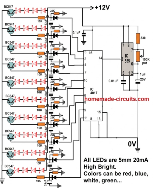
The working principle of this LED chakra circuit is based on the popular IC 4017 and IC 555 chaser circuit. The only difference being in the output driver stages, which has been upgraded with a delay OFF timer stage for introducing an eye catching slow fade effect.
The slow fade effect induces the required persistence of vision effect which we normally experience in real life rotating equipment such as fans, motor, vehicle wheels etc.
This allows the LED chakra to acquire a real shiny rotating metal kind of effect when it's placed behind the crwon of God idols.
Circuit Description
As mentioned above the design works with the IC 4017 which is Johnson's 10 stage decade counter divider IC, and a basic astable multivibrator IC 555.
The IC 555 oscillates at around 50 to 100 Hz rate (adjustable) and supplies the required clock pulses to the pin#14 of the IC 4017.
The IC 4017 converts the clocks into a momentarily ON shifting high logics across its output pins.
These moving logic levels are fed to the array delay OFF transistor stages which hold the sequential triggers for some moment instead of switching off immediately.
This enable the respective transistor stages to keep the LEDs ON for some time and provide the required rotational chakra like effect with a time lag.
Parts List
All resistors are 1/4 watt 5%
- 10K - 10
- 22K - 10
- 33K - 1
- 100K or 330k pot - 1
- 0.01uF - 1
- 0.1uF - 1
- 1uF/25V - 1
- 33uF/25V - 10
Semiconductors
- 1N4148 - 10
- BC547 - 10
- LEDs - 40
- IC 4017 - 1
- IC 555 - 1
If you have questions regarding the construction of this LED wheel chakra project, you may feel free to ask through the comments below.

Questions & Answers
can u share your contact number as i want to purchase
Sorry, I do not sell circuit kits nowadays, so you will have to build it yourself, if you face any issues, you can comment here, I will try to solve it quickly…
Good day, I have a couple of queries.
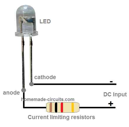
1) Should there be a 200 ohm resistor in series with each LED chain, assuming a current of 20mA and forward voltage of 2v per LED? (12-8)/0.02=200.
2) Can you please explain why the transistor base resistor values are so high given each one is only powering 4 LED’s with (possibly) a small resistor?
Many thanks.
1) If the supply is 12V constant then no need of any resistors for the LED because then each LED will get 12/4 = 3V which is optimal for a 3.3V LED.
2) 10K base resistor is not high, it is sufficient to provide 20 mA current for the LED string at the collector of the transistor.
Thank you for that explanation. However, I’m considering whether to use red and yellow LED’s, each one being 2v 20mA. So (12-(4×2))/0.02=200 if my math is correct.
Today all transparent clear LEDs are rated at 3.3V, but if you think your LEDs are 2V rated then you can add the 200 ohm resistor. It is correct.
I have double checked and the supplier website clearly says 2v/25mA(max) with a luminous intensity of 5000mcd for a 5mm red water clear led. The same supplier also has one rated 2.3v/70mA with a luminous intensity of 55000mcd. Could I use 4 of those in series with a 150 ohm resistor on each output or would I need to change each transistor+base resistor?
Using 4 of those at 12V would still be dangerous for the LEDs. They should be 3 V minimum. Better to put a limiting resistor in series, as previously calculated by you.
Yes, 70mA at 12v would dissipate about 0.8w so a physically large resistor would be required. I’ll try the 2v/25mA ones with a 200 ohm resistor and see how it goes.
OK, no problem.
Can you help will this project support more led,s per row of lights your circuit shows four lights will it support up to ten
You can add more strings of LEDs in parallel to the existing strings. Just replicate the LED strings associated with each transistor and connect them in parallel with the existing LED strings. Make sure to add a 22 ohm resistor with each LED string….considering the supply to be 12V
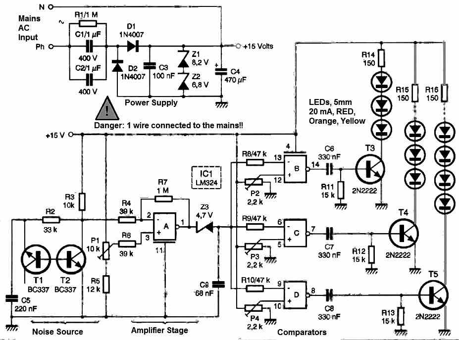
Dear i want to run 250-300 LED by AC volt. What can i do sir ?? No flashing needed just need to Run… I am using 75 of each Red,Green,Blue,Orange. Thanx for understandin.
Dipto, you can try the following circuit
you can make 3 strings having 75 led on each string, put the string ends in parallel, and connect it with the above power supply output…..make sure to have a 33 ohm resistor in series with each string,
And you can experiment with the nput capacitor value, try 0.47uF/400V or 1uF/400V until the rquired amount of illumination is achieved.
WARNING: THE CIRCUIT IS NOT ISOLATED FOR MAINS AC, PROCEED WITH CAUTION….
I am not sure about the connection of String….
2nd here have 2 capasitor which one i should experiment with??
Please tell me clearly .. Sir
Thanx Advance
Connect the LEDs in series with anode of one LED connecting with the cathode of the next LED…go on connecting in this way until you have a complete chain of 75 LEDs with anode and cathode as the end terminals of the chain…you can change the 0.33uF capacitor with other higher values to get higher illumination
you sure resistor values (222, 333, etc are accurate?) Should each R be tested? (to be sure the cascade is uniform?) Or does everything depend on rail (source) voltage?
Which are those resistors in the diagram, I can’t see any…
Dear Swagatam
I would like to request you to make a circuit diagram for me. I have an AV receiver which has only one set of RCA input. But I have 3 devices to connect with it. It will be of grey help if you design a 3 input 1 output RCA switcher in low budget.
Thanking you.
Regards.
Sangit.
Dear Sangit, I am sorry I do not have AV switcher circuit with me at this moment! If possible I’ll try to find it and update it here!