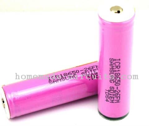
In this article I will try to explain the main specifications and datasheet of the Li-Ion cell 18650 2600 mAh, which is one of the most popular Li-ion batteries, and preferred by all electronic professionals due to its high efficiency, in terms power delivery and compact dimensions.
Li-Ion batteries are one of the most advanced forms of batteries which are designed to charge and discharge at high efficiency rates, compared to any other form of batteries.
Li-Ion batteries are able to charge significantly quickly by storing the voltage and current at almost 90% efficiency, and are able to deliver the same with almost the same amount of efficiency. That's the reason today all advanced and state-of-the-art gadgets depend on Li-Ion batteries for their functioning and performance.
In this article we are discussing the 18650 2600mAh Li-Ion Cells which look quite similar to the well known traditional AAA 1.5V cells, but are a lot more powerful and efficient with their ratings.
Difference Between AAA 1.5 Cell and 18650 2600 mAh Li-Ion Cell
The main differences between these two counterparts can studied as given below:
- AAA cells are rated at 1.5V whereas the 18650 2600 mAh cells are rated at 3.7V
- AAA cells are rated at maximum 1000 mAh, 18650 cells have the capacity as high as 2600 mAh
- Only Ni-Cd variants of AAA cells are chargeable with lower efficiency, while all 18650 2600 mAh are chargeable with great efficiency.
- AAA are mostly use-and-throw types having short life span, 18650 2600mAh have long life span and can be charged and discharged many 100 times with sustained efficiency.
Main Electrical Datasheet and Specifications
The main electrical datasheet and specifications of the 18650 2600 mAh cell can be understood from the following explanation:
- Nominal Voltage: 3.7V
- Maximum Ah rating: 2600 mAh
- Internal Impedance: around 70 milliohms
- Minimum Low Voltage Cut-off Limit: 3 V
- Recommended Full Charge or maximum Charge Cut-OFF Limit: 4.2V
- Recommended Charging and Discharging Rate: @0.52 Amps
- Possible Fast Charging and Fast Discharging Rate: @1.3 Amps at controlled case temperature
- Maximum allowable Charging and Discharging: @2.6 Amps in pulsed form and under controlled case temperature.
- Allowable Case Temperature range during Charging: 0 to 45 degrees Celsius
- Allowable Case Temperature range during is Discharging: -20 to 60 degrees Celsius.
How to Charge a 18650 2600 mAh Battery
Just as any other 3.7V Li-Ion battery , the 18650 2600mAh Battery must be charged with constant current constant voltage (CC/CV) rate, wherein the charger voltage must be rated at a constant 4.2V, and with a constant 0.52 ampere current.
The battery should be charged until its terminal voltage reaches 4.2V when the charging supply should be cut-off.
While discharging, an identical pattern as above must be followed wherein the connected load must be preferably rated to consume current at not more than 0.52 amps, and must be disconnected before the battery reaches around 3.1V.
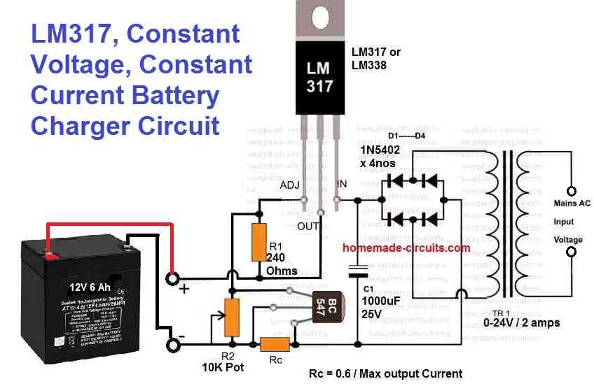
Simple (CC/CV) Auto cut-off Charger Circuit for Charging 18650 2600mAh Battery
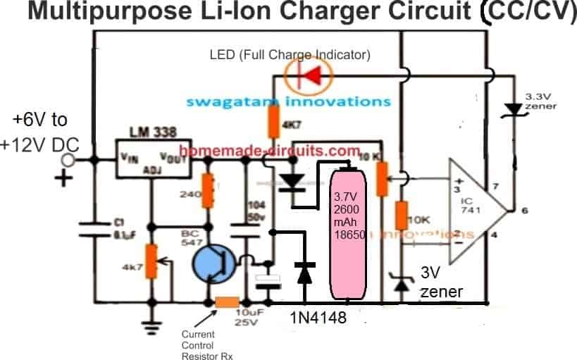
The above figure shows a simple 18650 2600mAh Battery charger circuit using a single LM317 IC regulator and an IC 741 based opamp stages.
Rx may be calculated as given below:
Rx = 1.2 / 0.6 = 2 ohm/ 1/2 watt
If you want to use fixed resistor instead of the 4k7 preset, you can calculated the same with the following formula;
VO = VREF (1 + R2 / R1) + (IADJ × R2)
where is = VREF = 1.25, R1 = 240 ohms, R2 = for 4k7 preset
Current ADJ is just 50 µA and therefore too small to be considered in the formula, you can remove it.
Alternatively you could also try this software
Setting up the circuit is easy
Keep the 10K preset slider to ground position. Apply minimum 6V at the input, and adjust the 4K7 pot to produce a precise 4.2V across the points where the battery is supposed to be connected.
Now, slowly adjust the 10k preset until the LED just lights up, seal the preset with epoxy glue.
Do this without connecting a battery.
That's all, the auto cut off system is all set now.
You can confirm the set up by attaching a discharged 18650 cell across the indicated points, then switch ON the supply, and wait until the red LED lights up. When this happens you can assume that the battery is fully charged, and can be removed for usage.
Simpler 18650 Charger Designs
As explained in other related post, charging Li-ion battery is not critical and can be done with a simple circuit, provided a couple of criteria are maintained.
The first condition is that the battery or the cell must be charged at a calculated constant current rate which does not heat up the battery above 37 degrees Celsius.
The second condition is to ensure the battery does not get overcharged and is cut off at exactly 4.2 V.
If an auto cut off charger seems difficult to build, this can be avoided simply by lowering the full charge threshold at 4.1 V. This level might slightly reduce the back up time, but nevertheless the battery will enjoy a good health, longer life, and moreover the charger could be built using ordinary parts or a single LM317 IC as shown below:
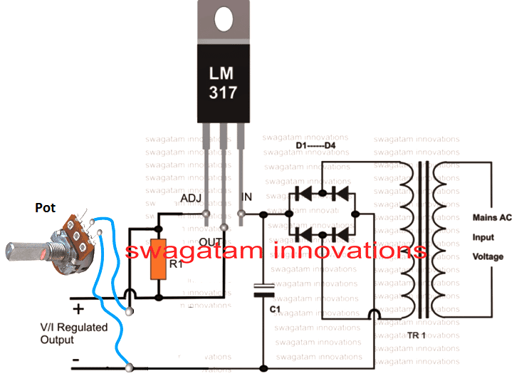
Adjust the pot to get an exact 4.1 V at the output for the 18650 cell.
- R1 = 240 ohms
- D1---D4 = 1N4007
- POT = 4k7 pot
- C1 = 1000uF/25 V
- Transformer = 0-6V/1 amp
Where can 18650 2600mAh Battery be Used
It can be used in all sorts of battery based applications which have to go through relentless power usage for a specific purpose, such as LED flashlights, emergency lights, drones and quadcopters, DC drill machines, hair trimmers etc.
These cells can be also effectively used in power bank circuits, an example power bank circuit can be seen below:
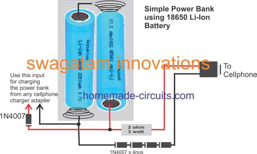
As we can see in the figure, two 18650 2600 mAh cells are connected in series inside a compact enclosure, and the output terminal are configured for charging the desired cellphone during emergency usage.
To render the power bank in ready or stand by position, it should be first charged using a charger that is explained in the previous section of this article. The input voltage must be set at 8.4V.
Once fully charged the power bank should be removed from the charger, during this time the battery voltage may drop to its standard level of 3.8V each constituting a total voltage of 7.6V.
The attached diodes make sure that the final output from the power bank is dropped to around 5.2V, while the 2 ohm resistor adds a current control feature to the output. This resistor value may need to be adjusted depending on the type of cellphone connected with the output, so that the charging is optimally and efficiently implemented
Once the above standby by state achieved, this 18650 2600mAh based power bank could be carried outdoors by the user for the intended emergency charging purpose.
Have questions? please ask them through the comment box below!


Questions & Answers
Hello, good afternoon, Mr. Swagatam. I have a question… Do you have a circuit to stop the deep discharge of 18650 batteries? I have two 18650 batteries in parallel, and I am using them to power a group of LEDs, but I want them to stop when they reach a safe discharge level… If possible, some kind of visual indicator would be better… Thank you very much in advance.
Good Morning Carlos, I think you can try the following circuit, and it should do the job for you, let me know how it goes:

Sorry. I intended to say a 5V 2.5A USB HUB Charger.
Hello Swagatam
I would like to know if it is possible to make a charging circuit for a Li-ion battery 18650 2000 mAh powered with USB 5V, with protection circuit of minimum discharge and overcharge.
And for one with 3800 mAh, is the charging current also 0.52 A or is there a mathematical formula to calculate the adequate charging current for each storage capacity?
Thank you in advance.
Hello Joao,
I think you can try the last circuit from the following article:
https://www.homemade-circuits.com/usb-automatic-li-ion-battery-charger/
This circuit will keep your battery charged fully and will cut off at 4.2V full charge level and will start recharging quickly when the battery voltage drops below 4.1V.
A good value for the charging current for li-ion batteries is 50% of its Ah value.
Hello Swagatam,
Thank you for Reply.
Best wishes,
Please sir, how can I construct power bank (battery) percentage indicators
Hi Theophilus,
I do not have this circuit at the moment, if I happen to design it I will surely let you know.
Atually I need this charger as I am working on a hand held soil moisture controller. So I need to save space using 11.1v 2200 mAH LI ion batteries to power the circuit and these batteries need to be charged with internal charging circuit.
So please help me.
Sorry, this cannot be built inside a very small space, because first of all you will need a 0-15V SMPS circuit, and then the SMPS output will need to be controlled through a 317 IC circuit as described by me previously, so I am afraid it cannot be a very compact system.
Hi,
I am looking for a circuit to charge 11.1v 2200 mAH Li ion cell. Can you please help me ?
The easiest way is to use an LM317 circuit and adjust the output voltage to 12.4V which is 0.2V less than the full charge level of 12.6V. The current can adjusted to 1 amp
An example design can visualized in the following figure. Let me know if you have anymore doubts.
Hello,
I have kind of a theoretical question: Batteries should be charged with a CC/CV rate. For me it’s clear that the voltage should be constant. But the current will be lowering until the4 battery reaches its maximun. So it’s more like constant voltage and limited current.
Is that right? Or I’m missing something?
Regards.
Pablo Frank
Hello, constant current refers to a feature of the charger where the output current is never allowed to increase over a specific limit. For example 5 amp CC may refer to a charger with a fixed 5 Amp current which can never exceed even if a short circuit is created at the output.
The battery stops consuming any current at full charge level because the charger output voltage becomes equal to the terminal voltage of the battery, and as we know when two sources have identical voltages, current cannot flow across these sources.
Thanks, very much, for your response. It’s very kind of you.
You are right, of course.
Mine was kind of a theoretical question. Now I think that the name or title “CC/CV” is misleading (or at least misled me), as neither current nor voltage are constant.
Best regards, and thanks again.
No problem at all, thanks for your feedback, appreciate it!
Hi
Could you give a breif descrition of how the charger circuit with the opamp is working as I’m getting no output from the opamp, I’m pretty sure I have it wired correctly, but dont know what to check to test why the led never lights. Are you using the opamp as a comparator?
Thanks Jase
Hi, you can remove the zener diode, since the LED itself is enough to prevent any leakage voltage from the op amp output.
For setting up do the following, without connecting any battery:
1) keep the pin 3 preset slider to ground level.
2) Adjust the LM338 preset to get exactly 4.2 V across the points where the battery would be connected
3) Now slowly adjust the op amp preset to just illuminate the red LED
That’s all your setting up is complete.
Now put a discharged battery, switch ON power, you will find the LED switched OFF and the LM338 output dropping to the battery level….now the battery will be slowly charging, as soon as the battery voltage reaches 4.2V, the LED will switch ON confirming the cut off and the full charge of the battery.
….remove the zener which is at the output of the op amp, in series with the LED
Hello Mr. Swagatam, thank you very much for your quick response. I think this circuit will work well… But I would like to know the power consumption, as it needs to be very low for good battery life.
Thanks Carlos, can you please tell me which image link are you referring to, is it one which I gave you earlier?

This circuit’s power consumption will be very low…it can be ignored
You can increase 1k value to 4.7k for even lower consumption
Thanks for the reply but the problem I have now is I am only getting about 20mA current when I have the battery connected, I have used the formular you’ve said in the text above of Rx = 1.2 / 0.4 for a 2000 mAh battery so I have a 3 ohm resistor for Rx so should’nt I be getting 0.4 A
How did you measure the current? for 2000 mAh, the Rx must be = 1.2 / 1 amp = 1.2 ohms, 2 watt. If you are measuring 20 mA without red LED glowing then maybe your LM338 is faulty.
Is the red LED glowing at the start, it must remain shut off, and glow only once the battery has charged fully.
Hi
I’m measuring the current with my bench top power supply which is powering the circuit.
In your description above I thought you were calculating Rx based on a c/5 rate which is why I did
1.2 / 0.4 is this not correct, the red led is’nt glowing at the start so I assume the transistor is off.
did you adjust the voltage across the battery at exactly 4.2V? you can remove the diode at the battery positive for the time being, and make sure the voltage across these battery points are 4.2V without battery connected. While adjusting this 4.2V make sure to disconnect the LED link to the base of the transistor.
C/5 rate will take many hours for the battery to charge, still it cannot be 20 mA even in this situation. 20mA shows that your battery is not accepting the charge….try connecting the ammeter between the LM338 output and the battery positive. Initially do not connect the LED link to the BC547 base…connect it only if the ammeter reads the correct optimal charging current.
pls advise :
door bell using dry cell 1.5 x 2
can I modify by using Adapter of Nokia 3,7 V 355 mA ?
Thanks
owen
Yes you can!
Hi there,
thanks for the great article. I have a 13 Ah, 36V, 10S5P, MX18650-26P Batterypack on my eBike. The guy I bought the battery pack from said that it can only be charged wit a current up to 2A. I would like to charge the battery pack with a solar panel with 160W. Given the formula 160W solar power / 42V battery charge voltage = 3,8A under optimal conditions (will almost never be the case). I don’t know if I can charge the cells with that kind of setup.
Can you help?
Hi, you can definitely use 3.8 amps since your battery is a Li-Ion battery, and 3.8 amp is fairly low current for charging it. You can safely use it without any issues.
Hi there, can I ask a question if you please? I have a cordless grooming clipper and the 2 batteries inside are 3.7v @750mA each and need replacing. Do they have to be @750mA or they can be replaced with higher Amp?
I do appreciate your answer, thanks and regards.
Hi, you can replace them with higher amps also, without any problems
Hello sir.
Please i need a power bank circuit diagram that can charge a lithium ion battery with the following spec:
Voltage 3.8v and 20ah(20000mah) capability.
Thanks.
Fredstev, you can charge the cell using an LM396 IC based circuit. You just have to adjust the output to 4.1 V
Hello Sir,
Its been quiet some time since i’m getting myself some old laptop batteries from the electronics market at reasonable rates.
Now I’ve had a good experience working with them.
I would like to point out certain things I’ve got to know and learn from them sometime later.
Firstly, i would say, if ever you lay your hands on any laptop battery pack, no doubts, you’ve got a pack of true lithium ion cells on them which are always real and branded.
Why, i say this is once a time i searched the internet for 18650 cells, you get a list of all types of cells, straight from branded to unbranded and also the very much fake ones from which you can really get cheated off.
But there are very few cells that are worth the cost, and the maximum are the fake ones.
The fake ones are described as :
1. colorful and eye catchy,
2. always print the highest capacity on them,
3. much lighter in weight when compared to original one
4. and are quiet cheap.
So i advise DIY’ers that those who want to use 18650 li-ion cells for projects, first try to search for old laptop batteries in the market; those have branded cells inside and you can reuse them for various projects.
One can also buy protected 18650 cells from the market or online, but based on their electrical parameters, they are much costlier compared to buying assembled 18650 battery modules mostly found in old laptop battery packs.
This is as per my experience when working with li-ion cells.
Thank you Sherwin for sharing this valuable information. Please keep up the good work!
hey swag,
I’d like to power a mosquito bat with 18650 3.7v batteries because the batteries in the AC rechargeable ones die quite fast. Of course I would lose the the AC recharging but I do have mutliple 18650 and a reliable xtar charger. The cells are NiCad totalling to 2.4v so I need to drop down the voltage. I was planning to use an LM317T but I found out that the min Vin – Vout = 3.0v but these are typically powered by 2.4v nicd. and that’s just a 1.3v difference, way below the the minimum voltage drop. Any recommendations on how I can drop down?
Hey Barns, just add a couple of 1N4007 diodes in series with the positive line of the battery, this will drop around 1.3V and give you the required 2.4V at the output.
good work sir.
from
Rx may be calculated as given below:
Rx = 1.2 / 0.6 = 2 ohm/ 1/2 watt
where did d 1.2 n 0.6 are from.
thanks.
Thanks Wale, they are the forward voltage drops of the BC547 and the 1N4148 diode at its base (0.6 + 0.6)….the potential drop across the Rx must overcome these two drops to trigger the BC547.
Nice job..
How to charge power bank?
Bcoz cell phone charger give only 5v..
I have 120 pcs of li_lion ???? pack but i dont know how i can make the circute using BMS to charge it collectry help me
You must specify the voltage and current of your battery!
You can use a 0-6V transformer and build a power supply with a bridge network and 2200uF filter capacitor, and use this adapter for charging the power bank