Normally, for standard 220V AC household projects, a single 600V or 800V TRIAC is more than enough. But what if you are working with a very high voltage line, like 1000V AC? A single common TRIAC will immediately burn and short circuit because it cannot handle that much voltage stress.
To solve this, we can connect two TRIACs in series. This divides the voltage load between them. However you cannot just tie them back-to-back blindly. If you do, they will burn out in microseconds due to small internal manufacturing differences.
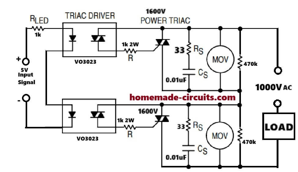
Let us look at a proper, working circuit diagram and understand how to build this setup safely without frying your components.
The Series TRIAC Circuit Diagram
Why its is Tricky to put TRIACs Directly in Series
When two TRIACs are in series, they act like two switches in a line. When they are turned OFF, the entire high voltage sits across them.
Because no two silicon chips are 100% identical, one TRIAC will always have slightly more internal resistance or less leakage current than the other. The less-leaky TRIAC will end up blocking the majority of the high voltage, crossing its limit, and exploding. Once the first one shorts out, the entire voltage slams into the second one, destroying it too.
Also when turning ON, one TRIAC will always fire a few nanoseconds faster than the other. The slower TRIAC will get hit by the full voltage spike and burn up instantly.
To fix these issues, we must add supporting components to force the voltage to stay perfectly balanced.
Components & Calculations
Main Power TRIACs In this circuit we use two 1600V Power TRIACs. Since our supply is 1000V AC, the actual peak voltage reaches around 1414V (1000 x 1.414). By stacking two 1600V parts, our circuit can theoretically handle up to 3200V, giving a huge safety margin.
Voltage Equalizing Resistors (470k) We connect a 470k resistor across the MT1 and MT2 terminals of each TRIAC. These resistors force the 1414V peak voltage to split exactly 50/50. Each TRIAC only faces about 707V peak when turned off.
Note: These resistors drop roughly 500V RMS each. Standard small quarter-watt resistors might catch fire or arc. You must use heavy-duty 2-Watt or 3-Watt metal oxide resistors here.
Optocoupler Drivers (VO3023) We cannot use standard MOC3041 drivers because they have built-in zero-crossing detection. Zero-crossing circuits cause a tiny time lag between the two stages, which destroys stacked TRIACs.
Instead, we use VO3023 random-phase optocouplers. They turn on at the exact microsecond the input signal arrives. The VO3023 is also rated for high blocking voltage, so it won't break down under the 750V peak stage stress.
Gate Resistors (R = 1k 2W) The gate resistors limit the turning-on current pulse coming from the line into the TRIAC gates. We use 1k resistors rated for 2 Watts.
This protects the internal phototriac inside the VO3023 from getting cooked by sudden high-current spikes.
Snubber Network (33 Ohm + 0.01uF) The RC snubber network absorbs sudden voltage changes (dv/dt) on the mains line. It prevents the TRIACs from accidentally turning themselves on when sudden heavy loads are switched elsewhere on the grid. The capacitors must be rated for at least 1000V DC.
MOVs (Metal Oxide Varistors) The MOVs are placed in parallel with each stage to clamp any massive voltage surges or lightning spikes before they reach the delicate silicon of the TRIACs.
Calculating the Input LED Resistor (Rled)
As you can see in the diagram, the internal LEDs of both optocouplers are wired in a series loop. This ensures that the exact same current triggers both drivers at the same time.
Because they are in series, their forward voltage drops combine. A single optocoupler LED drops about 1.3V. For two in series, the total drop is 2.6V.
If you are using a 5V DC input signal to turn the circuit ON, here is the formula to calculate your Rled value:
Rled = (Vin - (Vf1 + Vf2)) / Iled
Assuming we want a safe triggering current of 2.4mA:
Rled = (5V - 2.6V) / 0.0024A = 1000 Ohms (1k)
Final Layout Warning
When designing the actual PCB for this project, keep the high-voltage AC tracks physically far away from the low-voltage 5V DC input side. At 1000V AC, high-voltage noise can easily jump through tracking or close gaps, which can shock your microcontroller or control circuit.



Need Help? Please Leave a Comment! We value your input—Kindly keep it relevant to the above topic!