Today we are going to look into a very high efficiency resonant-mode off-line LED driver circuit. It is based on a very popular Infineon article which uses the IRS2530D DIM8 controller IC. Normally electronic ballast technology is used for old fluorescent tube lights, but here Infineon used the same concept to drive high power LEDs very efficiently. Let us see how this circuit works and its complete explanation.
Why Resonant Mode is Best
Instead of standard hard-switching where MOSFETs turn ON and OFF with full voltage and create lot of heat, this circuit uses Half-Bridge Series Resonant Tank topology.
In Zero Voltage Switching, the MOSFETs switch only when voltage becomes zero. So switching loss is almost zero and efficiency is very high. Because switching loss is not there, we can run the circuit at very high frequency. Due to this, the inductor and capacitor size becomes very small, so PCB footprint is reduced.
The LC resonant tank naturally controls the current based on frequency, so no need of complex primary side circuit.
Input Section AC to DC Converter
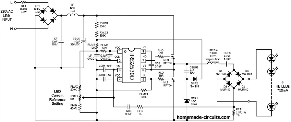
Look at the diagram, we can divide it into four main parts. The first is the input section which takes the 220VAC mains input and filters it. RF1 is a 0.47 ohm 0.5W fusible resistor. If any major short circuit happens, it will burn and protect your home wiring, and it also controls sudden inrush current.
BR1 is a 600V 0.5A bridge rectifier to change AC to DC. CF 47nF and LF 1mH form an EMI line filter which stops high frequency noise of the circuit from entering your house wiring. CBUS 10uF 350VDC is the main filter capacitor to get stable DC voltage.
Half Bridge and Resonant Tank Section
The second part is the Half-Bridge and Resonant Tank Section. MHS and MLS are two IRF730 N-channel MOSFETs. They switch alternately very fast to make high frequency square wave from the DC bus. LRES 2.3mH and CRES 4.7nF 1.6KV make the LC resonant tank.
It converts the harsh square wave into a smooth sine wave current. Note that the LRES inductor needs a strict 1mm air gap so the core does not saturate. CSNUB 1nF, DCP1, and DCP2 are the snubber and charge pump network. It helps in achieving ZVS and provides supply to the IC.
Control Section Using IRS2530D IC
The third part is the Control Section using the IRS2530D IC. In starting, VCC pin 1 gets power from DC bus via RVCC1 and RVCC2 startup resistors. Once the MOSFETs start switching, the charge pump takes over and gives power to the IC cheaply.
VCO pin 4 is connected to CVCO capacitor, and the voltage on this pin changes the internal oscillator frequency which drives the high-side and low-side MOSFET gates. DIM pin 3 is used for controlling the brightness and regulating the current.
Output Section and LED Load
The fourth part is the Output Section and LED Load. Since the resonant tank gives high frequency AC, we use four MUR160 ultra-fast rectifier diodes to make it DC again.
Normal diodes like 1N4007 will fail immediately here because speed is very fast. RCS is a 2.5 ohm 1W 1 percent current sensing resistor.
The voltage drop across this resistor tells the IC how much current is flowing in LEDs. This circuit is designed to easily drive 6 High-Brightness LEDs at 750mA constant current.
How Constant Current Dimming Works
LEDs always need strict constant current, otherwise they will burn. The IRS2530D manages this by changing the frequency. You set the current value using the potentiometer network consisting of RMAX, RPOT1, and RMIN. This gives a fixed DC voltage to the DIM pin.
When current flows through LEDs, an AC voltage is created across RCS resistor. This signal goes to the DIM pin through CFB and RFB. The IC checks this signal continuously. If LED current goes too high, the IC increases the frequency.
Higher frequency means higher impedance in LRES, so current automatically drops down. If LED current goes too low, the IC decreases the frequency closer to resonance, which increases the output current.
So it is a fully closed-loop automatic system. It is a very solid, high-efficiency SMPS LED driver project that you can easily build for long-lasting LED lights.


Need Help? Please Leave a Comment! We value your input—Kindly keep it relevant to the above topic!