• Skip to main content
  • Skip to primary sidebar

Homemade Circuit Projects

Need circuit help? Post them in the comments! I've answered over 50,000!

Blog | Categories | About | Hire Me | Contact | Calculators-online
You are here: Home / Datasheets and Components / 400V 40A Darlington Power Transistor Datasheet Specifications: MJ10022, MJ10023

400V 40A Darlington Power Transistor Datasheet Specifications: MJ10022, MJ10023

Last Updated on June 30, 2026 by Swagatam 6 Comments

In this post we investigate the datasheet and technical specifications of a 400V, 40A (ampere) power Darlington transistor MJ10022 and MJ10023, and also learn the main features of the device.

Table of Contents
  • Main Features
  • Maximum Absolute Ratings
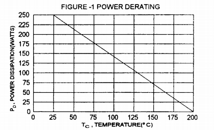
  • Thermal Dissipation Graph

We mostly find it difficult when it comes to finding a BJT with extreme voltage and current specifications such as with a 400V and 40 Amp limits.

Here's one such device which is rated with extreme V and I specs, yet it is easily accessible across local electronic markets. This power BJT could be applied in all DC high voltage and high current applications

This power transistor becomes even more special since it has an in-built Darlington feature ensuring maximum efficiency and high current gain, which allows the device to be switched with nominal input triggers and operate huge load using voltages upto 400V and current upto 40 amps.

Main Features

The BJT MJ10022 and MJ10023 are Darlington power transistors are designed to work with fast switching high voltage and high current inductive circuits in which the fall time are typically critical, such as in line operated SMPS topologies.

The main features of this device can be summarized as given below:

  • High current and high voltage operations
  • High speed switching
  • Incorporates high-speed base-emitter diode
  • Darlington high Gain output
  • Designed for heavy duty Inductive loads.

Maximum Absolute Ratings

  • Peak Collector-Emitter Voltage (Vcev) = 450V for MJ10022, and 600V for MJ10023
  • Sustained Collector-Emitter Voltage = 350V for MJ10022, and 400V for MJ10023
  • Maximum Emitter-Base Voltage (Vebo) = 8V
  • Peak Collector Current Icm = 80A (ampere)
  • Sustained Collector Current = 40A (ampere)
  • Maximum Base Current (Ib) = 20A (ampere)
  • Maximum Permissible Power Dissipation (Pd) = 250W (watts) at 25 degrees Celsius, and 143W (watts) at 100 degrees Celsius.

Thermal Dissipation Graph
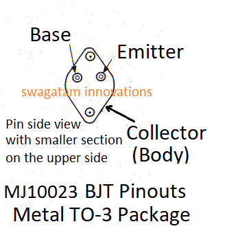
Pinout Diagram of MJ10022, and MJ120023 (similar to any other TO3 package such as 2N3055)
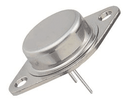
Actual Image of the Discussed 400V 40A BJT MJ10022/MJ10023
You'll also like:

  • IC 4020 Datasheet, Pinout Functioning Explained
  • IC 4001 Datasheet, Pinout, Applications
  • BQ24295 Smart Battery Charger IC with Boost + OTG
  • Isolated High Side Gate Driver Opto-Coupler HCPL3120: No need of Bootstrapping Capacitor/Diode

Filed Under: Datasheets and Components Tagged With: 400V, 40A, Darlington, Datasheet, Power, Transistor

About Swagatam

I am an electronics engineer and doing practical hands-on work from more than 15 years now. Building real circuits, testing them and also making PCB layouts by myself. I really love doing all these things like inventing something new, designing electronics and also helping other people like hobby guys who want to make their own cool circuits at home.

And that is the main reason why I started this website homemade-circuits.com, to share different types of circuit ideas..

If you are having any kind of doubt or question related to circuits then just write down your question in the comment box below, I am like always checking, so I guarantee I will reply you for sure!


Previous Post: « Make this IR Remote Control Range Extender Circuit
Next Post: Cell Phone Ring to Flashing Lamp Indicator for People with Hearing Loss »

Reader Interactions

Questions & Answers

Total Posts: 6
Newest Oldest
Nwibo sylvestet
January 6, 2018 • 9 years ago #57407

Your circuits diagrams are pretty real. I wish to come over to India and run a full electronics course with you.

Reply
SwagatamAdmin
January 7, 2018 • 9 years ago #57417

Thank you!!

Reply
Waleed Fareed
February 1, 2018 • 8 years ago #58183

Please help me
I have cnc router spindle with specification:
3 phase
Volt = 220 V AC
Freq. = 400 Hz
Power = 800 W
I need low cost driver circuit
thanks in advance
Speed = 24000 RPM

Reply
SwagatamAdmin
February 1, 2018 • 8 years ago #58194

the easiest way is to put 3 separate triac based dimmer controllers (regulators) in series with the 3 lines of the 3 phase.

then synchronize the pots of the 3 dimmers such that when you want to control the speed, all the 3 knobs rotate together in a synchronized manner

Reply
PGV
February 1, 2018 • 8 years ago #58202

Hello Swagatam,

I have gone through many circuits you have designed especially Inverter ones. All I am confused is with the Simple Ohm’s Law and the Power Outputs !!!
If you have time, please go through my concept here :

We have a 12 Volt (7 AH battery / whatever the current ratings – I simply don’t know)
Need to make an Inverter to run an Old sewing machine(manual) support motor (90W, 220/230V/0.5A,50/60Hz)
This motor is in turn mechanically connected to another motor to work as a generator – (I tried one which generates only 150 Volts ac ; Don’t know the current and frequency generated )
This 150 Volts I need to further use for an inverter to generate more power..
Do you think this is possible or a bad Idea ??? If possible, I wonder HOW??

I am also running after the ways of sustainable free Energy..
I appreciate your valuable time to read this…
Wish your thoughts to be positive….
Thank you so much..
Have a Joyful Time Ahead… 🙂

Reply
SwagatamAdmin
February 2, 2018 • 8 years ago #58210

PGV, that can be never possible, if you have seen such concepts on YouTube, consider them as fakes…

Reply

Need Help? Please Leave a Comment! We value your input—Kindly keep it relevant to the above topic! Cancel reply

Your email address will not be published. Required fields are marked *

Primary Sidebar


My Youtube Channel

Circuit Simulator

circuit simulator image


Subscribe to get New Circuits in your Email


Categories

  • Arduino Projects (95)
  • Audio and Amplifier Projects (134)
  • Automation Projects (18)
  • Automobile Electronics (103)
  • Battery Charger Circuits (88)
  • Datasheets and Components (109)
  • Electronics Theory (149)
  • Energy from Magnets and Earth (40)
  • Games and Sports Projects (11)
  • Grid and 3-Phase (20)
  • Health related Projects (27)
  • Home Electrical Circuits (13)
  • Indicator Circuits (16)
  • Inverter Circuits (100)
  • Lamps and Lights (162)
  • Meters and Testers (72)
  • Mini Projects (28)
  • Motor Controller (68)
  • Oscillator Circuits (28)
  • Pets and Pests (15)
  • Power Supply Circuits (91)
  • Remote Control Circuits (50)
  • Security and Alarm (65)
  • Sensors and Detectors (107)
  • SMPS and Converters (45)
  • Solar Controller Circuits (61)
  • Temperature Controllers (43)
  • Timer and Delay Relay (50)
  • Voltage Control and Protection (44)
  • Water Controller (37)
  • Wireless Circuits (31)


Other Links

  • Privacy Policy
  • Cookie Policy
  • Disclaimer
  • Copyright
  • Videos
  • Sitemap

People also Search

555 Circuits | 741 Circuits | LM324 Circuits | LM338 Circuits | 4017 Circuits | Ultrasonic Projects | SMPS Projects | Christmas Projects | MOSFETs | Radio Circuits | Laser Circuits | PIR Projects |


Recent Comments

  • Swagatam on DPDT Relay Working, Pinouts, Testing Explained
  • Swagatam on DPDT Relay Working, Pinouts, Testing Explained
  • Swagatam on Inverter LC Filter Calculator
  • Swagatam on Notch Filter Circuits with Design Details
  • Nare Mashiachidi on DPDT Relay Working, Pinouts, Testing Explained

Social Profiles

  • Twitter
  • YouTube
  • Instagram
  • Pinterest
  • My Facebook-Page
  • Stack Exchange
  • Linkedin

© 2026 · Swagatam Innovations