In this article we will see how an Arduino based RFID reader circuit could be used for controlling a relay, which in turn could be used in security door lock applications.
Overview
If you haven’t yet checked the previous RFID article, please go ahead check it out, it covered the basics of RFID technology.
We are going to identify the authorized tags using UID. In a nutshell UID is the unique identification number of the tag, when you scan your card at your office or anywhere else, it extracts the UID from the card.
The UID of the card is saved on the database of your office and it will recognize the card holder and register your attendance.
The tag not only transfers UID, but also transfers some other information which is stored in the tag, the tags can generally store from 1KB to 4KB sometimes even more.
We won’t be discussing how to store information on the tag but, it will be discussed in a future article. In this post we are going to utilize the UID number to control the relay ON/OFF.
The motto of this project is to turn ON/OFF the device, which is connected with the given setup on scanning with authorized RFID tag.
The UID of the card is defined in the program and when authorized card is detected, it will turn on the relay on the first scan and scanning it again will deactivate the relay.
If any unauthorized card is detected, it will give out error message on serial monitor and relay continue its current task without any interruption.
Here when the authorized card is scanned, the relay activates/deactivates, this mechanism can be used anywhere, for example in: door locking system, where authorized card needs to be scanned to open door.
How it Works:


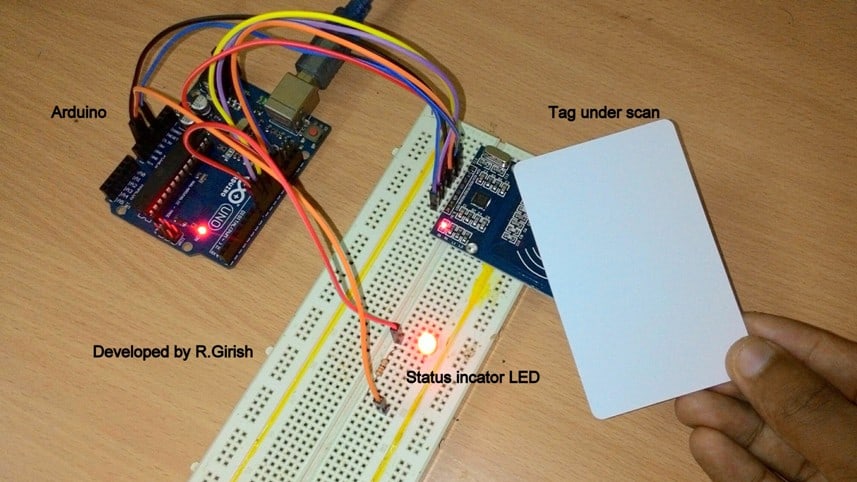
The RFID circuit consist of LED which indicate the status of the relay, BC 548 transistor drives the relay and 1N4007 diode is connected across the relay to arrest the high voltage spike at the instant of switching.
If you want to connect higher voltage rated relay (9V or 12V), you can connect external +Ve supply to relay and –Ve supply to ground of arduino’s GND pin. Please take at most care while proceeding this step, as you may damage the board if connections are not right.
The next step after completing the hardware setup is to upload the code to find the UID of you tag.
Now upload the below given program to arduino, open serial monitor and scan the tag.
Program to find UID:
#include <SPI.h>

#include <MFRC522.h>

#define SS_PIN 10

#define RST_PIN 9

MFRC522 rfid(SS_PIN, RST_PIN);

MFRC522::MIFARE_Key key;

void setup()

{

Serial.begin(9600);

SPI.begin();

rfid.PCD_Init();

}

void loop() {

if ( ! rfid.PICC_IsNewCardPresent())

return;

if ( ! rfid.PICC_ReadCardSerial())

return;

MFRC522::PICC_Type piccType = rfid.PICC_GetType(rfid.uid.sak);

if(piccType != MFRC522::PICC_TYPE_MIFARE_MINI &&

piccType != MFRC522::PICC_TYPE_MIFARE_1K &&

piccType != MFRC522::PICC_TYPE_MIFARE_4K)

{

Serial.println(F("Your tag is not of type MIFARE Classic, your card/tag can't be read :("));

return;

}

String StrID = "" ;

for (byte i = 0; i <4; i ++) {

StrID +=

(rfid.uid.uidByte[i]<0x10? "0" : "")+

String(rfid.uid.uidByte[i],HEX)+

(i!=3?":" : "" );

}

StrID.toUpperCase();

Serial.print("Your card's UID: ");

Serial.println(StrID);

rfid.PICC_HaltA ();

rfid.PCD_StopCrypto1 ();

}
The output on serial monitor (example):
Your card’s UID is: AA:BB:CC:DD
On the serial monitor, you will see some hexadecimal code, which is the UID of the tag. Note it down, which will be used in the next program to identify the tag.
After this step is completed, upload the below code on the same setup.
Program to identify the card and control relay:
//---------------Program developed by R.Girish------------//
#include <SPI.h>
#include <MFRC522.h>
#define SS_PIN 10
#define RST_PIN 9
int flag=0;
int op=8;
char UID[] = "XX:XX:XX:XX"; //Place your UID of your tag here.
MFRC522 rfid(SS_PIN, RST_PIN);
MFRC522::MIFARE_Key key;
void setup()
{
Serial.begin(9600);
SPI.begin();
rfid.PCD_Init();
pinMode(op,OUTPUT);
}
void loop()
{
if ( ! rfid.PICC_IsNewCardPresent())
return;
if ( ! rfid.PICC_ReadCardSerial())
return;
MFRC522::PICC_Type piccType = rfid.PICC_GetType(rfid.uid.sak);
if(piccType != MFRC522::PICC_TYPE_MIFARE_MINI &&
piccType != MFRC522::PICC_TYPE_MIFARE_1K &&
piccType != MFRC522::PICC_TYPE_MIFARE_4K) {
Serial.println(F("Your tag is not of type MIFARE Classic, your tag can't be read :("));
return;
}
String StrID = "" ;
for (byte i = 0; i <4; i ++)
{
StrID +=
(rfid.uid.uidByte[i]<0x10? "0" : "")+
String(rfid.uid.uidByte[i],HEX)+
(i!=3?":" : "" );
}
StrID.toUpperCase();
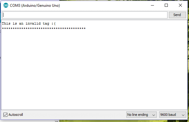
if(StrID!=UID)
{
Serial.println("This is an invalid tag :(");
Serial.println("***************************************");
delay(2000);
}
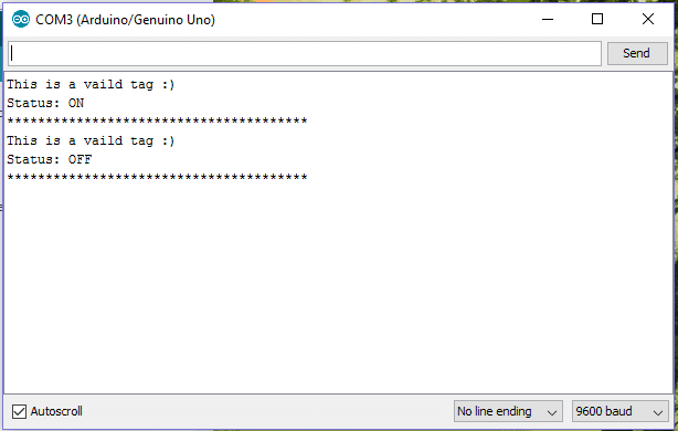
if (StrID==UID && flag==0)
{
flag=1;
digitalWrite(op,HIGH);
Serial.println("This is a vaild tag :)");
Serial.println("Status: ON");
Serial.println("***************************************");
delay(2000);
}
else if(StrID==UID && flag==1)
{
flag=0;
digitalWrite(op,LOW);
Serial.println("This is a vaild tag :)");
Serial.println("Status: OFF");
Serial.println("***************************************");
delay(2000);
}
rfid.PICC_HaltA ();
rfid.PCD_StopCrypto1 ();
}
//---------------Program developed by R.Girish------------//
char UID[] = "XX:XX:XX:XX"; //Place your UID of your tag here.
Replace XX:XX:XX:XX with your UID.
Author’s prototype which can be effectively used as a foolproof RFID security lock for doors and safes:
When an authorized card is scanned:
When an unauthorized tag is scanned:
If you have any questions regarding this Arduino RFID security lock circuit, please feel free to ask below in comment section.
Hi there! Code compiling with ATmega 2560, but not working.
Hey, please check it now, and let us know if still it has problems.
Hi Swagatam, Just wondering if there is any way that I could add more tags into the code, I have 3 different tags that I would like to use.
Regards
Geoff
Hi Geoff, I'll forward the question to the author of the article Mr. GR for the solution.
Thank you Swagatam, shall wait for a reply.
Hi geoff,
Yes it is possible to add 2 more tags. I will try to update the code.
Regards