In this article I have explained a simple circuit idea which can be applied in order to convert existing car park lights into advanced, smart DRL system. The idea was requested by Mr. Chris.
Technical Specifications
I was very interested in reading the circuit diagram you posted a few months back regarding the 'Smart DRL/indicator circuits' (https://www.homemade-circuits.com/2014/04/smart-car-drl-controller-circuit.html)I was wondering if you could help me modify this circuit ever so slightly for my own project? I only have a basic knowledge of electrical circuits/PCBs and need some slight assistance.
Essentially I am trying to replicate this system:
https://www(dot)youtube(dot)com/watch?v=X51b_d4d6KQ
Thanks for your time!
Regards,
Chris
The Design
The referred video clipping shows the following effects over the modified park lights which are now replaced with LED DRLs.
When the turn signals are switched ON, the relevant DRL partially shuts off so that the turn signal flashing becomes more prominent and highlighted.
The moment turn signals are switched OFF, the DRL is automatically reverted to its original brightness, however the transition is not instant rather in a slow and gradually increasing manner (reverse fading).
The above procedure is repeated each time the turn signals are switched ON, either left/right sides individually or together.
Upgrading Park-Lights to DRL
The proposed upgradation from park-lights to an enhanced DRL circuit for producing the above effects can be done by implementing the shown circuit below.
First of all the park lights will need to be replaced with LED DRL modules, and next the proposed circuit should be used in conjunction for the required enhancements.
The operation of the circuit is pretty straightforwardand may be understood as under:
The relay stays in a deactivated position as long as head lamp or the turn signals are not activated.
Under this situation the N/C contacts allow the +12V (from ignition switch) to reach the switching transistor base which in turn keeps the connected DRL illuminated brightly or normally through its emitter voltage.
Now in case either the head lamp or the turn signal is switched ON, the relay is supplied with the toggling voltage and it activates, shifting its contact from N/C to N/O
The breaking of the N/C contacts stops T1 from conducting and the DRL is inhibited from the direct 12V supply, instead now it connects through the relay N/O and the 317 current controlled stage such that its glow gets much weaker or as as per the selected R1 value
In the meantime C1 is discharged completely via R3.
Next, the moment the relevant lights are switched OFF, the relay switches OFF and reverts to its original deactivated position, connecting the 12V supply back to the base of T1.
However here T1 is forced to conduct slowly due to the presence of C1 which does not allow T1 to switch ON quickly, producing the required reverse fading of the DRL until its full bright.
Circuit Diagram
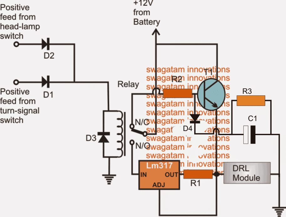
Parts List for the above circuit design
R1 = (1.25/DRL amp value) x 3
R2 = 1k 1/4 watt
R3 = 10K
C1 = 470uF/25V
T1 = TIP122
D1, D2, D4 = 1N4007
D3 = also 1N4007 (optional)
Relay = 12V, 400 ohms, SPDT
Feedback from Mr. Chris
Hi Swagatam,
Thank you very much for working this out for me - a great explanation, diagram, and bill of materials!
I just have a few simple questions:
1. The 12v feed from the indicator switch will have to come from the indicator stalk where there is a constant 12v, and not the intermittent/flashing 12v after the flasher relay, is this correct?
2. The 'DRL module' on your diagram - I assume this is just the white LEDs? Is there a maximum amount of LEDs that I can utilise or do I just have to adjust the resistor values accordingly?
3. If I was to add the 'indicator module' (orange LEDs) to this unit, as per the video, I assume I would just have to take the 'flashing' 12v feed from the existing flasher relay into a resistor, then the LEDs, and then to ground?
Thanks again for your time, it is much appreciated.
Kind regards,
Chris
Analyzing the Issue
Hi Chris,
Thanks!
Here are the answers to your questions:
1) Ideally it should be a fixed 12V which could be taken from the flasher On/OFF dashboard switch, if a flashing feed is used, the relay coil of my circuit will need to be stabilized with a 1000uF/25V capacitor in parallel so that the relay does not get rattled with the fluctuating 12V feed rather stays constantly switched ON.
2) LED configuration could be specific to the DRL unit that I have not addressed in the article, here the current (amp) consumption is what matters, which shouldn't exceed 1amp, if it does then the TIP122 may need an upgradation.
3) yes, just hook up the orange LEDs with an appropriate current limiter stage, and you can directly wire it up with the existing flashing DC source from the flasher unit.
Best Regards.
Comments
Hi, can you tell me how to wire this to a automotive relay that have the pins 30, 85, 86, 87 and 87a
You can easily find that through a search on Google, for example I could find this diagram:
http://www.olct.co/images/News/Understanding_Relays/ISO_Mini_Relay_Pinout.jpg
but automotive relay i not recommended for the above project due to the unnecessary high current consumption by its coil
How will one signal right and left
one more question why the value of R2 is 1 k for slow rising and 10k for instant rising, should not be the same for the base of T1
you can use 10k in the above circuit also for R2, it'll make the switchON slower than 1k
Hi, is i use the other circuit homemadecircuitsandschematics.blogspot.ro/2014/04/smart-car-drl-controller-circuit.html#comment-form
will turn on DRL slow, because 470 uF capacitor will charge in 4,7 sec(10k resistor), and to turn on i must use a smaller capacitor 4,7uF,
is true?
if it' s not , the what is for C1 there,
in this second circuit with D1 and R3 , added if i wanna turn on fast just replace capacitor ?
so my question is can i use first circuit without D1 and R3 to open fast and slow DRL only by replacing C1
In the above circuit the turn OFF will be fast but turn ON will be slow, for an opposite effect just shift the capacitor to the left of R2 and don't use D4, R3
in the other linked article, both turn ON and turn OFF will be slow depending on the value of the cap selected
Hey Swag. Just wanted to make sure you haven't forgot about me. No rush at all just a friendly reminder.
Thanks for reminding me Chris, it's already been published, please find the design here:
https://www.homemade-circuits.com/2014/06/modifying-car-turn-signal-lights-park.html
Hello Swagatam. I have a project that is slightly related to this one and could use your help.
I have 2 single filament bulbs that I would like to use as parking lights as well as turn signals. They would be wired to stay on anytime the car is running, and each light would turn off and on when the corresponding turn signal is activated. The wire from factory the turn signal harness controls the +12 side. I also have 2 single filament bulbs that I would like to use as side markers anytime the parking lights are on, and I want them to flash opposite the turn signal, so when the turn signal bulb is lit the side marker is off, and when the turn signal bulb is not lit, the side marker bulb is. The side markers will not be lit unless the parking lights are on, but I do still want them to flash anytime the turn signals are activated. I prefer not to use led's as my project is striving for a retro look, but I might if it's not possible with the incandescent bulbs.
Thanks
Chris R
Hello Chris, I'll try to publish the design soon, and let you know as soon as it gets posted. Thanks!