• Skip to main content
  • Skip to primary sidebar

Homemade Circuit Projects

Need circuit help? Post them in the comments! I've answered over 50,000!

Blog | Categories | About | Contact | Calculators-online
You are here: Home / Indicator Circuits / Up/Down LED Indicator using LM3915

DIY Circuits | Learn Basics | Arduino Coding


Up/Down LED Indicator using LM3915

Last Updated on January 8, 2024 by Swagatam 2 Comments

This circuit can be used for moving an LED bar graph in the upward sequence or downward sequence through a couple of push button switches. The concept can be implemented for many other useful applications.

Using IC LM3915

In many circuit applications we require a digitally operated control system enabling an upward or downward control of a particular parameter, such as for controlling heat, sound volume, PWM, motor speed etc.

The application need may look straightforward but implementing it practically might not be that easy, unless specialized (hard to find) ICs are involved.

Here we'll see how the same may be achieved with the help of the IC LM3915 which is very commonly available across the globe and is reasonably cheap.

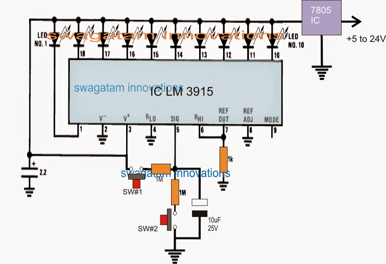
Understanding the proposed up/down LED sequence controller circuit using push button is very easy, and may be done by referring to the above figure.

How it Works

The image shows a LM3915 LED bar graph driver IC, configured in its standard mode.

Ten LEDs can be seen connected across the ten outputs of the ICs.

The LEDs are supposed to illuminate one after the other in a straight sequence from pin#1 to pin#10 of the IC, in response to a rising potential across its pin#5, meaning as long as the potential at pin#5 is zero, all the LEDs can be assumed to be switched OFF, and as the potential at pin#5 is increased, the LEDs may be seen illuminating sequentially from pin#1 until pin#10.

Pin#10 LED illuminates when the potential at pin#5 reaches about 2.2V.

The sequencing of the LEDs can be in the dot mode (when pin#9 is open) or in the bar mode (when pin#9 is connected with the positive supply).

In the above design since the pin#9 is not used or is unconnected, the sequencing of the LEDs are in the dot mode, meaning only one LED is lit at any instant across the relevant pinout of the IC.

For implementing the up or down sequence, SW#1 or SW#2 needs to be manually pressed.

When SW#2 is pressed, the capacitor across pin#5 of the IC is allowed to discharge slowly, causing the potential to drop gradually until may be it reaches 0V.

In response to this the LED sequence may be seen "running" backwards" from pin#10 to pin#1.

Conversely when SW#1 is pressed, the 10uF capacitor is allowed to get charged gradually which prompts the IC outputs to push the LED sequencing from pin#1 towards pin#10.

Thus the two push buttons may be appropriately pressed and released for achieving any one desired pinout of the IC to be in the active state, depending upon the charge level of the pin#5 capacitor.

The idea can be implemented for many other similar applications simply by integrating the control stage with the various pinouts of the IC in the required sequence.

You'll also like:

  • Low voltage Indicator 1IC 741 Low Battery Indicator Circuit
  • LEDMusicLightCircuitDiagram252CImageSimple LED Music Level Indicator Circuit
  • car radiator indicator circuit 1Car Radiator Hot Indicator Circuit
  • IC 4049 pinout diagramSimple Water Level Indicator Circuits (with Images)

Filed Under: Indicator Circuits Tagged With: Down, Indicator, LED, LM3915

About Swagatam

I am an electronics engineer and doing practical hands-on work from more than 15 years now. Building real circuits, testing them and also making PCB layouts by myself. I really love doing all these things like inventing something new, designing electronics and also helping other people like hobby guys who want to make their own cool circuits at home.

And that is the main reason why I started this website homemade-circuits.com, to share different types of circuit ideas..

If you are having any kind of doubt or question related to circuits then just write down your question in the comment box below, I am like always checking, so I guarantee I will reply you for sure!

Previous Post: « LED Strip Light Dimmer Controller Circuit
Next Post: PWM Motor Soft Start Circuit to Prevent High Consumption during Power Switch ON »

Reader Interactions

Comments

ade says:
May 28, 2020 at 7:39 am

that’s brilliant im so glad you have done this I now have the up down led controls for my power indicator on the startrek phaser type 2 im building fantastic this was the missing part now to put it all together.

Reply
Matrix says:
May 28, 2020 at 10:32 am

Hi, the circuit does not work properly due to quick capacitor leakage.

you will need to add the following circuit at pin5 of the LM3915 to make it work correctly.
up down touch switch control potentiometer

Reply

Need Help? Please Leave a Comment! We value your input—Kindly keep it relevant to the above topic! Cancel reply

Your email address will not be published. Required fields are marked *

Primary Sidebar

circuit simulator image


Subscribe to get New Circuits in your Email


Categories

  • Arduino Projects (93)
  • Audio and Amplifier Projects (133)
  • Automation Projects (17)
  • Automobile Electronics (101)
  • Battery Charger Circuits (85)
  • Datasheets and Components (109)
  • Electronics Theory (149)
  • Energy from Magnets (27)
  • Games and Sports Projects (11)
  • Grid and 3-Phase (20)
  • Health related Projects (27)
  • Home Electrical Circuits (13)
  • Indicator Circuits (16)
  • Inverter Circuits (95)
  • Lamps and Lights (159)
  • Meters and Testers (71)
  • Mini Projects (28)
  • Motor Controller (68)
  • Oscillator Circuits (28)
  • Pets and Pests (15)
  • Power Supply Circuits (91)
  • Remote Control Circuits (50)
  • Renewable Energy (12)
  • Security and Alarm (64)
  • Sensors and Detectors (106)
  • SMPS and Converters (34)
  • Solar Controller Circuits (60)
  • Temperature Controllers (43)
  • Timer and Delay Relay (49)
  • Voltage Control and Protection (42)
  • Water Controller (36)
  • Wireless Circuits (30)


Other Links

  • Privacy Policy
  • Cookie Policy
  • Disclaimer
  • Copyright
  • Videos
  • Sitemap


People also Search

555 Circuits | 741 Circuits | LM324 Circuits | LM338 Circuits | 4017 Circuits | Ultrasonic Projects | SMPS Projects | Christmas Projects | MOSFETs | Radio Circuits | Laser Circuits | PIR Projects |

Social Profiles

  • Twitter
  • YouTube
  • Instagram
  • Pinterest
  • My Facebook-Page
  • Stack Exchange
  • Linkedin


Recent Comments

  • Swagatam on 9 Simple Solar Battery Charger Circuits
  • Gagana on 9 Simple Solar Battery Charger Circuits
  • Swagatam on Arduino 2-Step Programmable Timer Circuit
  • Swagatam on Simple Buck-Boost Converter Circuits Explained
  • Swagatam on IC IR2111 H-Bridge MOSFET, IGBT Driver IC: Full Datasheet, Circuit Diagram

© 2026 · Swagatam Innovations