In this article I have explained Ohm's Law and Kirchhoff's Law through standard engineering formulas and explanations, and by applying linear first-order differential equation to solve example problem sets.
What's an Electric Circuit
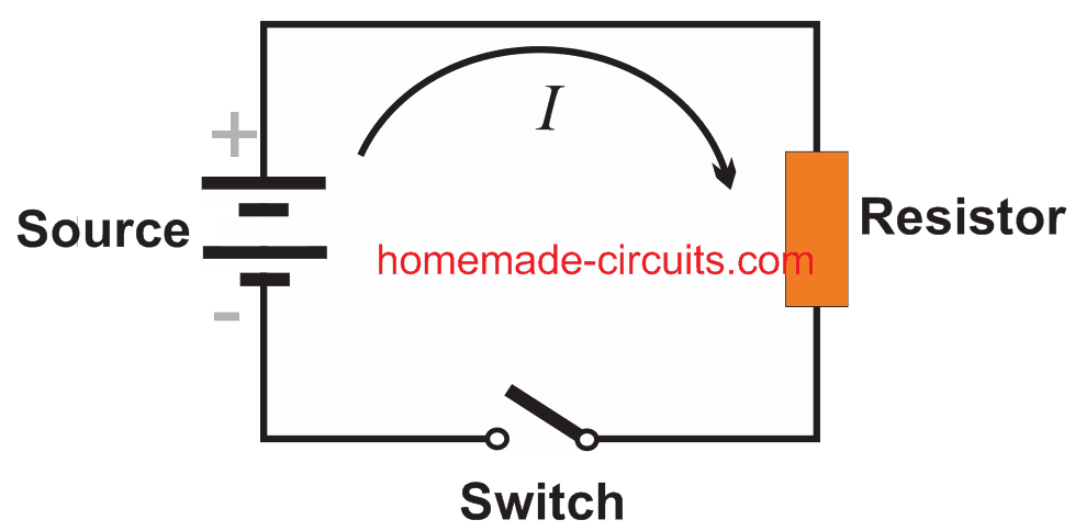
A simplest electric circuit is generally in the form of a series circuit having an energy source or electromotive force input, like from a battery, or a DC generator, and a resistive load which consumes this energy, for example an electric bulb, as shown in the diagram below:
Referring to the diagram, when the switch is closed, current I passes through the resistor, causing a voltage to generate across the resistor. Meaning, when measured, the potential differences at the two end points of the resistor will show different values. This can be confirmed using a voltmeter.
From the above explained situation the standard Ohm's law can be deduced as:
The voltage drop ER across a resistor is proportional to the instantaneous current I, and may be expressed as:
ER = RI (Equation#1)
In the above expression, R is defined as the constant of proportionality and is called resistance of the resistor.
Here we measure the voltage ER in Volts, the resistance R in Ohms, and the current I in amperes.
This explains Ohm's law in its most basic form within a simple electric circuit.
In more complex circuits, two more essential elements are included in the form of capacitors and inductors.
What's an Inductor
An inductor may be defined as an element that opposes a change in current, creating an inertia like effect in the flow of electricity, just like a mass does in mechanical systems. Experiments have yielded the following for inductors:
The voltage drop EL across an inductor is proportional to the instantaneous time rate of change of the current I. This may be expressed as:
EL = L dl / dt (Equation#2)
where L becomes the constant of proportionality and is termed as the inductance of the Inductor, and is measured in henrys. Time t is given in seconds.
What's a Capacitor
A capacitor is simply a device that stores electrical energy. Experiments enable us to get the following explanation:
The voltage drop across a capacitor is proportional to the instantaneous electric charge Q on the capacitor, this may be expressed as:
EC = 1/C x Q (Equation#3)
where C is termed as the capacitance, and is measured in farads; the charge Q is measured in Coulombs.
However since I(C) = dQ / dt, we can write the above equation as:
The value of current I(t) can be solved in a given circuit by solving the equation produced by the application of the following physical law:
Understanding Kirchhoff's Law (KVL)
Gustav Robert Kirchhoff (1824-1887) was a German physicist, his popular laws may be understood as narrated below:
Kirchhoff's Current Law (KCL) states that:
At any point of a circuit the sum of the inflowing currents is equal to the sum of the outflowing current.
Kirchhoff's Voltage Law (KVL) states that:
The algebraic sum of all the instantaneous voltage drops around any closed loop is zero, or the voltage impressed on a closed loop is equal to the sum of the voltage drops in the rest of the loop.
Example#1: Referring to the RL diagram below, and by combining the Equation#1,2 and the Kirchhoff's voltage we are able to derive the following expression:
Equation:4
Let's Consider this case A with a constant electromotive force:
In the above described equation#4 if E = E0 = constant, then we are able to drive the following equation:
Equation: 5
Here the last term nears zero as t tends to proceed to infinity, such that I(t) tends to the limiting value E0/R. After an adequately long delay, I will get to a practically constant, without depending on the value of c, which also implies that this will be independent of an initial condition that may be forced by us.
Considering the initial condition to be, I(0) = 0, we get:
Case B (Periodic Electromotive Force):

Considering E(t) = Eo sin ωt, then by taking Equation#4 into account the general solution for Case B can be written as: (∝ = R / L)
Integrating it by parts gives us:
![]()
This can be further derived as: ઠ = arc tan ωL / R
Here the exponential term tends to approach zero as t tends to reach infinity. This implies that once adequately long period of time has passed, the current I(t) attains a practically harmonic oscillations.


Need Help? Please Leave a Comment! We value your input—Kindly keep it relevant to the above topic!