• Skip to main content
  • Skip to primary sidebar

Homemade Circuit Projects

Need circuit help? Post them in the comments! I've answered over 50,000!

Blog | Categories | About | Contact | Calculators-online
You are here: Home / Lamps and Lights / Single IC Dimmable Ballast Circuit

Single IC Dimmable Ballast Circuit

Last Updated on January 1, 2024 by Swagatam 2 Comments

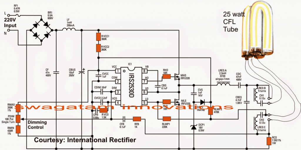
In this post I have explained a simple 25 to 36 watt ballast circuit which can used for all fluorescent tube applications within the allocated range.

Table of Contents
  • The Preheater Stage
  • The Charge Pump Circuit
  • The Dimmer Stage
  • Ensuring 100% Ignition

warning message: electricity is dangerous, proceed with caution
electronic ballast circuit with dimmable feature

The circuit of the proposed electronic fluorescent ballast may be understood through the following discussion:

The Preheater Stage

The half-bridge stage comprising the two mosfets are triggered by the IC for initiating the required preheating of the tube filaments and for striking the tube into complete illumination.

An instant start is facilitated by the presence of RVCC1 and RVCC2 by providing the required start-up current to the positive line of the circuit.

The Charge Pump Circuit

In the meantime the charge pump section made by CSNUB, DCP1 and DCP2 takes control of the situation while the IC begins oscillating.

LRES and CRES form the resonant tank circuit and are responsible for generating a high voltage for the transition functions useful for the igniting the tube. It also helps to provide a low-pass filtering intended for the dimmable action of the tube.

You would also witness a DC blocking capacitor CDC intended to keep the lamp current at an AC potential which is important for preventing mercury merger and lamp blackening at the ends as a result. The feature ensures longer lamp life with great intensities.

LRES:A,B are the secondary winding inside in the resonant coil which are included for optimal preheating of the filaments and also for implementing the featured dimmable actions.

It also allows the use of a single resistor RCS for the required current sensing by extracting an isolated current supply from the filament source. This current sensed across RCS is applied to the DIM pinout of the IC via a feedback loop made by a resistor, capacitor network: CFB and RFB.

The Dimmer Stage

The dimming network includes a potentiometer control which essentially provides a varying reference voltage to the DIM pin of the IC enabling the dimming of the lamp to any desired level manually.

RLMP1 and RLMP2 are positioned for detecting the presence of the lamp that may be used at the output.

As soon as the lamp connection is detected by this stage the circuit initiates the above discussed functions, instantly illuminating the tube to its optimal intensity.

Ensuring 100% Ignition

In addition to the above, the IC IRS2530D has some outstanding in-built features such as 100% ensured ignition of the connected tube and a sustained constant illumination of the tube even under low voltage conditions from the mains input. Moreover all these are achieved by using very few number of components.

Thanks to International Rectifier for providing us with the discussed single chip electronic ballast circuit.

Circuit Diagram

You'll also like:

  • 1.  Rechargeable LED Lantern Circuit Using Dynamo
  • 2.  40 watt Electronic Ballast Circuit
  • 3.  Infrared (IR) LED Flood Light Circuit
  • 4.  10 Automatic Emergency Light Circuit Diagrams Explain
  • 5.  Electronic Candle Flame Simulator Circuit
  • 6.  Simple PIR LED Lamp Circuit

Filed Under: Lamps and Lights Tagged With: Ballast, Dimmable, Single

About Swagatam

I am an electronics engineer and doing practical hands-on work from more than 15 years now. Building real circuits, testing them and also making PCB layouts by myself. I really love doing all these things like inventing something new, designing electronics and also helping other people like hobby guys who want to make their own cool circuits at home.

And that is the main reason why I started this website homemade-circuits.com, to share different types of circuit ideas..

If you are having any kind of doubt or question related to circuits then just write down your question in the comment box below, I am like always checking, so I guarantee I will reply you for sure!

Previous Post: « 4 Automatic Staircase Lamp Controller Circuits Explained
Next Post: Grid-tie Inverter (GTI) Circuit Using SCR »
Subscribe
Notify of
guest


guest
2 Comments
Inline Feedbacks
View all comments

Primary Sidebar

circuit simulator image

Subscribe to get New Circuits in your Email

Categories

  • Arduino Projects (90)
  • Audio and Amplifier Projects (132)
  • Automation Projects (17)
  • Automobile Electronics (101)
  • Battery Charger Circuits (83)
  • Datasheets and Components (106)
  • Electronics Theory (143)
  • Free Energy (37)
  • Games and Sports Projects (11)
  • Grid and 3-Phase (19)
  • Health related Projects (25)
  • Home Electrical Circuits (12)
  • Indicator Circuits (15)
  • Inverter Circuits (89)
  • Lamps and Lights (142)
  • Meters and Testers (71)
  • Mini Projects (46)
  • Motor Controller (64)
  • Oscillator Circuits (28)
  • Pets and Pests (15)
  • Power Supply Circuits (108)
  • Remote Control Circuits (50)
  • Security and Alarm (64)
  • Sensors and Detectors (103)
  • Solar Controller Circuits (59)
  • Temperature Controllers (42)
  • Timer and Delay Relay (49)
  • Transmitter Circuits (29)
  • Voltage Control and Protection (40)
  • Water Controller (36)

Other Links

  • Privacy Policy
  • Cookie Policy
  • Disclaimer
  • Copyright
  • Videos
  • Sitemap

People also Search

555 Circuits | 741 Circuits | LM324 Circuits | LM338 Circuits | 4017 Circuits | Ultrasonic Projects | SMPS Projects | Christmas Projects | MOSFETs | Radio Circuits | Laser Circuits | PIR Projects |

Social Profiles

  • Twitter
  • YouTube
  • Instagram
  • Pinterest
  • My Facebook-Page
  • Quora
  • Stack Exchange
  • Linkedin
  • Recent Comments

    • Swagatam on Understanding Capacitor Codes and Markings
    • Swagatam on Mains High Low Voltage Protection Circuit with Delay Monitor
    • Swagatam on 3 Phase Induction Motor Speed Controller Circuit
    • Swagatam on Smart Bathroom Exhaust Fan Controller Circuit with Sensors
    • James Williams on 3 Phase Induction Motor Speed Controller Circuit

    © 2025 · Swagatam Innovations