This proximity detector circuit uses a Hall effect sensor to detect the approach of a magnetic object, such as a magnet fixed to the frame of a door. The application is simple, but widely used.
The use of a Hall effect sensor solves many problems that arise when one wants to detect the opening of a door or window using a simple micro-switch.
A Hall effect sensor is primarily sensitive to magnetic fields, so it is entirely possible to bury the sensor or hide it behind materials permeable to magnetic fields (such as a wooden board or plasterboard).
The electronics associated with the sensor in our design have sufficient sensitivity to enable it to detect a small magnet placed over five centimeters from the sensor.
In these conditions, the installation of the system is not really a constraint and should give you access to numerous home automation applications.
Circuit diagram
The proximity detector using hall effect sensor is shown in figure 1 below.

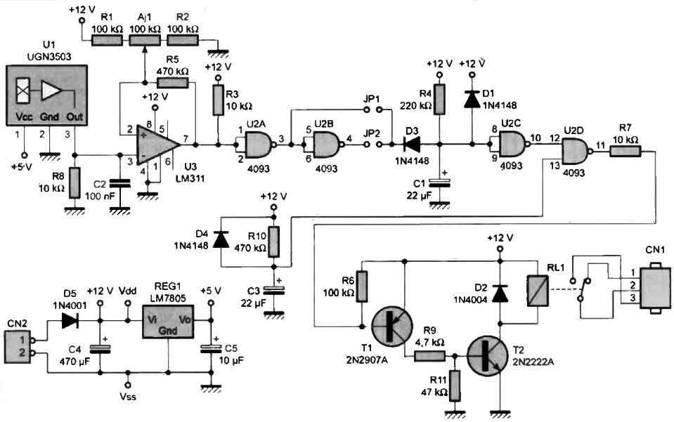
We chose to use a Hall effect sensor with a linear output, in order to be able to adjust the operating point of the system ourselves. Our choice naturally fell on the UGN3503 sensor, due to its wide distribution.
In the absence of a magnetic field, the output voltage of the U1 sensor is approximately Vcc/2. When the sensor is subjected to a magnetic field, its output voltage deviates from Vcc/2 with an amplitude proportional to the magnetic field (about 1.30 mV/Gauss). By using a comparator mounted in Schmitt trigger, the use of such a sensor is very simple.
The R8 resistor modestly charges the sensor and provides the signal to the (-) terminal of comparator U3. The Aj1 potentiometer adjusts the reference point of the comparator, while the R5 resistor introduces hysteresis in the switching thresholds (Schmitt trigger effect).
The output of U3 is shaped a second time by gates U2A and U2B, which allow you to choose the polarity of the system using JP1 or JP2. Depending on the direction of the magnetic field imposed on the sensor, the output voltage of U3 will switch to the "high" or "low" state as the magnet approaches.
To easily reverse the direction of magnetic field detection, we used gates U2A and U2B. The JP1 and JP2 straps allow you to choose the desired detection direction (which is sometimes easier than reversing the direction of the magnetic field).
Whenever the magnetic field exceeds the threshold set by Aj1, capacitor C1 is discharged via D3. The diode D3 allows capacitor C1 to recharge later through R4, which produces a well-defined time constant.
When capacitor C1 is discharged (strong magnetic field), the output of U2C goes to the "high" state for an approximate duration of T = 0.7 x R4 x C1.
As long as the magnetic field is sufficient, the output of U2B (or U2A depending on the strap) maintains the discharge of capacitor C1. The timing introduced by R4/C1 begins when the magnetic field becomes too weak. Diode D1 protects the input of U2C during power cuts by quickly discharging C1.
The signal from U2C is then inverted by U2D in order to control the relay through the command stage formed by T1 and T2. This command stage is composed of two transistors to allow the R10/C3 network to inhibit the relay command when the circuit is powered on via U2D.
The R10/C3 network has a time constant twice that of the R4/C1 cell to cover the charging time of Cl at power-up. This ensures that the relay will not be driven during this time.
The relay control is a classic of its kind, so we will not dwell on this subject. It should simply be noted that since the coil of a relay is inductive, diode D2 is necessary to demagnetize it when the command is cut and to protect transistor T2. The circuit is partly powered by a 12 VDC voltage which does not need to be stabilized.
A properly filtered voltage will suffice provided it can supply a current of 150 mA (when the relay is active). Diode D5 protects the circuit in case of reverse polarity of the power connector, which allows for peace of mind during the installation of the device. The regulator REG1 provides a +5V voltage necessary for the operation of the U1/UGN3503 integrated circuit.
Construction
The layout of the printed circuit board is shown in Figure 2 below.
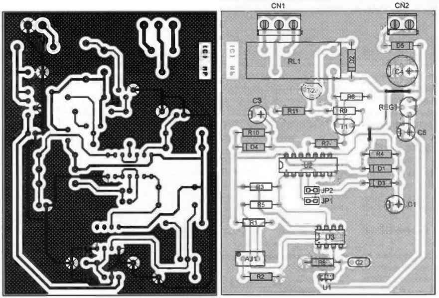
The pads will be drilled with a 0.8 mm diameter drill bit, for the most part. Regarding REG1, D2, and D5, a 1 mm drill bit will be needed. Finally, concerning the relay, a 1.3 mm drill bit should be used.
Before etching the printed circuit board, it is advisable to obtain the components to ensure that they are properly installed. This remark concerns particularly the relay and the adjustable resistor Aj1. Be careful with the orientation of the components and follow the nomenclature carefully.
Do not forget to install the necessary straps for the proper operation of the circuit. Since it is a relatively simple circuit, you should not encounter difficulties during the installation, except for finding the orientation of the U1 sensor.
The right layout image will help you identify the pins of the UGN3503 sensor.
Depending on the direction of the magnetic field you wish to detect, you will need to install either the JP1 or JP2 strap. But be careful, do not install both straps at the same time, as you would short-circuit the U2B gate, and there is a good chance that the U2 circuit would be damaged.
Instead of the strap, you can solder a wire directly onto the printed circuit board (in place of JP1 or JP2). In this case, it is advisable to test the circuit with the final magnet before installing it in its final location. This will allow you to ensure that the magnetic field is properly detected depending on the orientation of the magnet.
Note that it is possible to replace the U2 circuit with a CD4011, which slightly modifies the time constants chosen for this circuit, but this is still acceptable.
Finally, note that it is possible to move the U1 sensor 10 to 20 centimeters away from the circuit without any difficulty. This can be useful if you want to install the circuit in a cramped location.
Need Help? Please Leave a Comment! We value your input—Kindly keep it relevant to the above topic!