This is probably the simplest radio receiver circuit that one could ever imagine of making. The circuit is so simple that it could be finished assembling within a few minutes and you are already listening your favorite programs over it.
Introduction
What are the fundamental criteria associated with radio reception? An antenna stage, a band selector stage, a demodulator stage and a receiving element.When all of these come together radio reception becomes as simple as a piece of cake.
The circuit of a single transistor radio shown here though looks pretty ordinary, yet incorporates all the above stages and becomes just suitable for receiving the nearby radio stations.
However simplicity will always involve some drawbacks also, here the present design will be capable of receiving only strong stations and also selectivity might not be very pleasing, typically if there are a couple of strong stations mingling around the band.
Circuit Operation
The figure below shows how the single transistor radio can be made, we can clearly see that it just involves a single transistor as the main active component.A regular type of MW antenna coil has been used for collecting or sensing the MW receptions.
The coil is tuned using a GANG condenser or a variable capacitor which is connected in parallel to the antenna coil.The coil and the GANG together form a resonant tank circuit, which lock on to the received or the resonant frequency at a particular setting.
The concentrated but very low in power signal from the above LC tuned stage is fed to the base of the transistor which as performs the function of a demodulator as well as a amplifier stage.
The coupling capacitor at the base of the transistor makes sure only the radio information passes to the transistor while the DC component from the supply is appropriately blocked.
Headphone Becomes the Load and the Switch
A 64 Ohm headphone becomes the collector load of the transistor, where the demodulated and amplified signal is applied.
When connected, the received signals can be distinctly heard over the headphones with this little “audio marvel”Plugging in the headphone initiates the circuit and the circuit starts operating with its functions and the switches OFF itself when the headphone is removed from the circuit.
This eliminates the need of an external switch to be associated with the circuit, making the unit very compact.
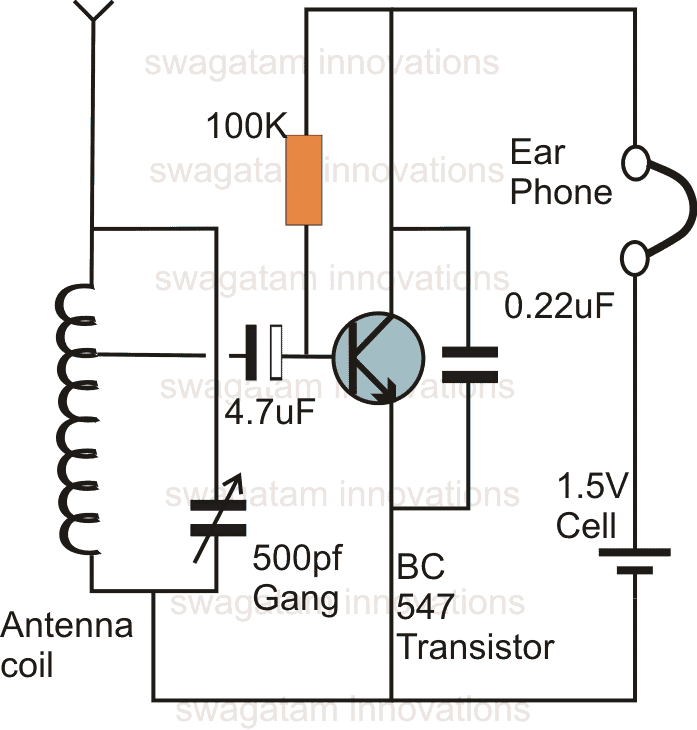
The circuit requires just 1.5 V for operating which can be implemented using a single button type of cell.
You would also want to build this ONE TRANSISTOR FM RADIO CIRCUIT
Feedback from one of the avid readers of this blog, Mr. SA Genoff
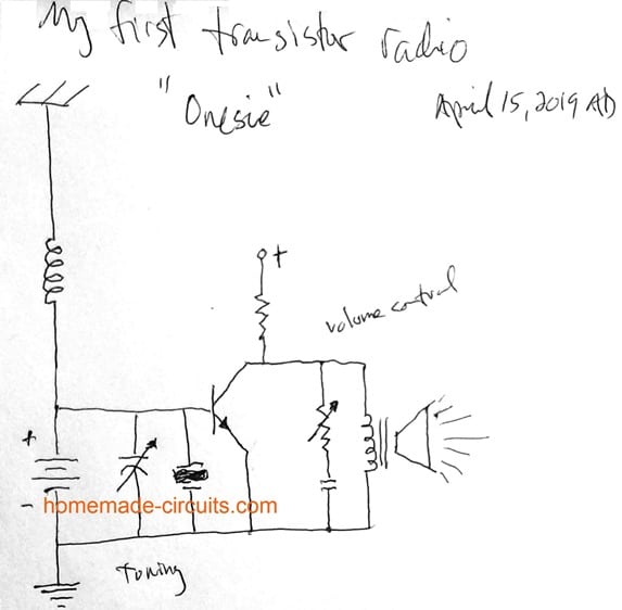
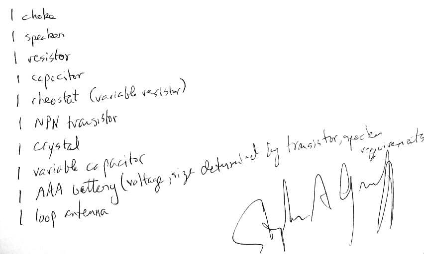
Could you take a look at my 1st design of a single transistor radio ? Attached is a photo of my work.I have not studied Electronics extensively, just some undergraduate Physics and math. I know Ohm's law and am familiar with Maxwell's equations, but not conversationally.
Thanks so much for your work and webpages, Stephen A Genoff
My Reply:
Why there are two positives? Perhaps the battery should be replaced by the coil. Did you try it practically, how did it respond? The volume control part also may be incorrect according to me!



Questions & Answers
Hi, i tried to build this radio but I couldn’t hear anything , even radio static, what is a possible issue ?
Hi, do you have a strong AM radio station nearby in your area, if not then this circuit won’t respond. In that case you can try a two transistor radio as explained in the following article:
https://www.homemade-circuits.com/simplest-am-radio-receiver-with-speaker/
Can i use a High impedance earphone instead to hear weaker signals ?
Yes, higher impedance earphones will give you a better response…
Dear Swagatam, is there a way to see what frequency this receiver is tuning to?
Thanks
Hi Osvaldo, the only easy way would be to calibrate the GANG dial with the frequency bands using another parallel radio switched to the same stations.
Do you supply or can you refer me to a kit supplier for this single transistor radio?
I would buy 16 kits.
Thank you
JM
Sorry, I do not supply kits. I have no idea regarding who can do this for you!
Hello, I’m familiar with all the circuit elements in this schematic, but I was wondering what the line going from the middle of the inductor from the antenna directly to the 4.7 micro-Farad capacitor meant. In my mind I would have a physical wire attached from the middle of the inductor then going into said capacitor, but I don’t think that’s right. How should I wire this component?
Hi, you can use the antenna coil center tap wire itself, and solder its stripped end with the capacitor negative terminal, any extra wire is not required.
hi
Looking for schematic/design for RF Amplifiers:
A) Hollow State low safe Plate Voltages (B+) for retrofitting Antique 1920; 2 and 3 DIALER TRF RADIOS
B) Solid State Transistor/Semiconductors
STEAMPUNK/Retromodern/Hybrid Radios
————————————————————————-
STEAMPUNK/Retromodern/Hybrid Radios Grammarly
Hi
Looking for comment; advice; assistance; for my Senior Citizens SWL/Scanner/DXing Club’ STEAMPUNK/Retromodern/Hybrid Rado Receiver/Objet d’art/Plural Objets d’art Project(s)
A) To Retrofit/Restore, Antique/Vintage TRF & Regenerative Receivers to use a low, safe, Plate voltages.
B) To Build, Breadboard style, Crystal, TRF and Regenerative Radios using Antique/Vintage Tuning Components with modern electronics to come up with Objets d’art Sculptures; as well as Functional Radios.
Steampunk combining Antique Components with Modern Electronics The basic idea is to give the user the “feel ” of 1920’s multiple Tuning Controls with modern stable electronics.
The need for assistance is coming up with simple basic RF Amplifier schematics.
Tubes and/or Transistors especially circuit designs using 12 volt Space Charge Tubes.
Plan A: All solid State
Plan B: All Hollow State
Plan C: Hybrid is Hollow State RF with Solid State Detectors and Audio Amplifiers.
For Antique/Vintage Radios the plan is to remove all high voltage Tubes and use the Hardware Chassis Tuning Components and wiring and use RF & Audio Modules/PC Boards; Hollow State and/or Solid State; mounted on dead tube bases. Minimal disruption to original circuitry so as to be able to reverse changes to allow a conventional restoration. Hybrid comes in with Hollow State for the RF Stages and Solid State Transistor/semiconductor pcboard/modules for Detector and Audio; readily available on eBay.
The need for assistance is coming up with simple basic RF Amplifier schematics to build PC Board/Modules Tubes and/or Transistors as well as circuit designs using low plate voltage Tubes.
thanx 73 de jordan ve7jjd
[email protected]
Hi, I will try to help wit the mentioned TRF and radio circuits, I have plenty of such designs available with me…..I’ll try to post them through a dedicated article soon.
Could I get permission to use the schematic of the one-transistor radio you published at
https://www.homemade-circuits.com/make-this-one-transistor-radio-receiver/
I am working on a book on magnetism for NASA and it will be used free of charge by teachers and students!
Thanks!!
Please feel free to use it, I have no objection to it!
Hi Swag,
The antenna coil, what are the specifications? Turns, wire diamanter, ferrite core size?
Hi Nelio, you can find the details in the following article:
https://www.homemade-circuits.com/mini-transceiver-circuit/
Hi,
Thanks.
Best Regards.
Nélio.
You are welcome Nelio
what is the maximum range of the reciever, is it AM or FM?
It is AM, range is 20 km to 30 km maximum
What is that, “onsie”?
Can I use Bc237 and 8 ohm 0.25w speaker ???
yes you can try
You sure 8 ohm speaker works ????
In the last circuit you can replace the speaker coil with a small output transformer and then use a small speaker. or you can try the designs from this article;
https://www.homemade-circuits.com/simplest-am-radio-receiver-with-speaker/
If I use 47 ohm resistor collector to speaker, can I Use 8 ohm speaker ????
Could you describe the coil used for your receiver
How many turn for each frequency?
Could you give us a formula ?
I will try to build this receiver for my little son
Thank you in advance
It is an antenna coil which is normally used in MW radios
Wish you all the best!
I can use s9018 instead of BC 547
yes you can
ser what is 500 pf gang
please make video for explan it
ser please tell me about every component of this FM circuit
please show me pic of every component and tell me its full name like pf etc.
and tell me its values please please
praveen, this is not FM, it is an AM circuit, if possible I'll update it with the required details.
ser please tell me about every component like trangister, ressisters,capictor etc.
ser please show me a pic of very component
ser also tell me full name of every component and its values
like 500 PF GANG what is this tell me all please please
The schematic is wrong,the capacitor in the base of tranzistor isn't eltrolythic,is a 100 nF ceramic capacitor
sorry, your assumption is not correct.
Hi, I have made this circuit but it is unable to catch any FM signals (I just need to catch 1 channel).
can you tell me coil's specifications (thickness, diameter and turns) ?
Hi, This is not a FM receiver, it's an AM radio.
in this circuit it could be for 3 reasons:
to stabilize the 1.5V when a strong reception is detected,
to ground unwanted high frequency response and to make the audio clearer.
to safeguard te transistor from earphone coil back emfs…
can you please tell me why we wire capacitor between colcector amd ameitter?
to keep the voltage stabilized and maintain the selected frequency….
what is the height of the antenna
the longer the better….2 meters can be tried initially.
Good day sir
Will this capture FM signals?
I used BF199-based replacement Transistor istead of BC547. and used Standard FM Tunning Gang CAP paralleled to Standard MW AM antenna coil.
Will this work?
Good day PSK, I don't think it's designed for reeving FM, it's specifically intended for MW reception
I made this and it is working. Fed the signal into a LM386 and can hear it on a 8ohm speaker. Too bad I can only 2 clear stations.
Can you say anything about the power consumption of this circuit?
Thanks in advance!
sorry but you should put the question under the relevant article, because i have so many transmitter related articles, can't really figure out which circuit you are referring to.
anyway all my circuits are correct and will surely work if done correctly.
Please excuse me, I actually wanted to ask you, how good the quality of your published receiver is?
I wanted to ask you that question, because I intend to build your fm receiver and a fm transmitter.
From last one (transmitter), I want to transmit an audio signal to a pair of headphones, which I want to make wireless due to your receiver circuit?
You know what I mean? – Basicly I just wanted to know, what you think about this idea and if the quality is good enough.
Sorry, I did not understand your question, what an FM receiver has to do with the above circuit?
The above circuit is a receiver not a transmitter
Okay, thank you for your informations!
– but I still have one another question about your circuit:
What do you think – how is the quality of the received sound, if I build a FM receiver just some meters next to the receiver? – do you think, the sound will be good or have you any other idea, how I could realise this?
I'm asking, because I want to make a pair of headphones wireless – but with power consumption as low as possible.
Thank you in advance, Mr. Majumdar!
not sure, but the 1.5V cell would last for years.
you said you can be hired, if we pay you. will you thumb my bum while watching german piss porn for $50? i dont have hair on my balls.
I'll do it free of cost for you, however may be you won't appreciate my service as I would come armed with a red hot iron and nutcracker equipment…..be ready