In this post I have explained how to make an illuminated LED cricket stump and bails for helping umpires declare a foolproof OUT, NOT-OUT decisions.
The Circuit Concept
You might be seeing these amazing cricket stumps in the ongoing 2015 ICC world cup cricket matches, which can be seen dazzle or light up brightly as soon the ball hits any one of the stumps.
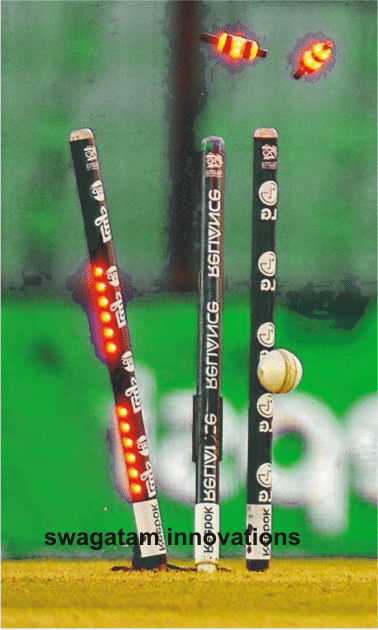
It's invented by an Australian person named Bronte EcKermann and created by South Australian manufacturer Zing International.
It is said that the cost of these stumps may be as high as US$ 40,000 for each set, gosh!. The circuit of these LED stumps is assumed to be consisting of all sorts of complex designs using microcontrollers.
In this article we'll learn how each of these circuits can be built using ordinary components at less than $5 and yet be as effective as the original LED stump specs.
LED Bails Circuit
The first diagram below shows a circuit which may be employed inside the bails, the idea may be understood as follows:
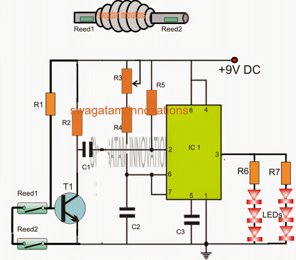
The IC1 which is an IC 555 is configured as a monostable wherein R3 and C2 along with R4 decides the ON time of the LEDs.
An NPN transistor T1 can be seen attached with pin2 trigger input of the IC, whose base is rigged with a couple of reed switches in series.
The idea is simple: The entire circuit is required to be fixed inside each of the bails with the reed switches enclosed inside the end tubes of the bails. Furthermore, a permanent magnet needs to be fixed at the upper ends of the stumps so that the reed switches remain closed for so long as these are held over the stumps.
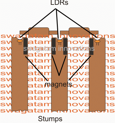
The figure above shows how the magnets inside the stumps needs to be embedded and positioned for the bails to respond to these.
As long as the bails are held over the stumps, the reed switches stay closed ensuring a switched OFF T1. However the moment the bail is completely dislodged from the slots, allows the reed switches to open and switch ON T1 which in turn triggers the monostable illuminating the LEDs for a time period as determined by R3/R4/C2. The LEDs remain shut off until these are yet again positioned over the stumps for a repetition.
That takes care of the bail circuitry, pretty simple.... isn't that?
In the above diagram we can also see LDRs being positioned right at the top of the stumps just under small apertures that my be drilled on top surfaces of the stumps.
These LDRs become exposed to the ambient external light the moment the bails are dislodged from the slots. since these LDrs are supposed to be integrated with sets of identical monostables inside the stumps, the operation becomes responsible for illuminating the LEDs attached on the stumps, thus the entire system consisting of the stumps and the bails become synchronized providing a foolproof sequence of the proceedings.
UPDATE:
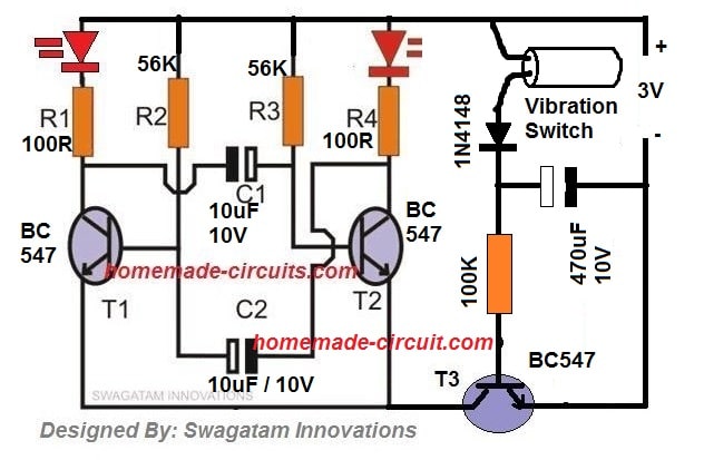
Hey friends, today I made the LED bail design even simpler by using transistors instead of an IC. The advantage of this circuit is that it can work even with a 3 V supply and also blink the connected LEDs during its ON period. Additionally, I have ensured that the standby current of the circuit is negligibly low (while these are mounted on the stumps)
Here's the new circuit diagram for your viewing pleasure!

Important: Please keep both the reed switches together on a single arm of the bail and linked with a single magnet on the stump, instead of installing them across the opposite arms of the bail. Because both the reed switches need to close while they are placed on the stumps, if one of the reed is open then the circuit might not respond correctly.
Video Proof or the Test Results of the above LED Bail
Parts List
- R1, R4 = 100 Ohms
- R2, R3 = 56K
- R5, R6 = 10K
- R7 = 330K
- C1, C2 = 10uF/6V
- C3 = 1000uF/6V
- T1, T2, T3 = BC547
- T4 = BC557
- Miscellaneous = Reed Relay switches, 3V Button Cell
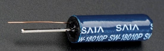
The above LED Bail circuit can be further simplified by using a vibration switch, as shown below, although I doubt the accuracy level may not be as good as the reed relay version.
Vibration Switch Image
Circuit Diagram
LED Stump Circuit
The following circuit shows how the circuit inside the stumps needs to be configured for implementing the LED stump circuit operations.
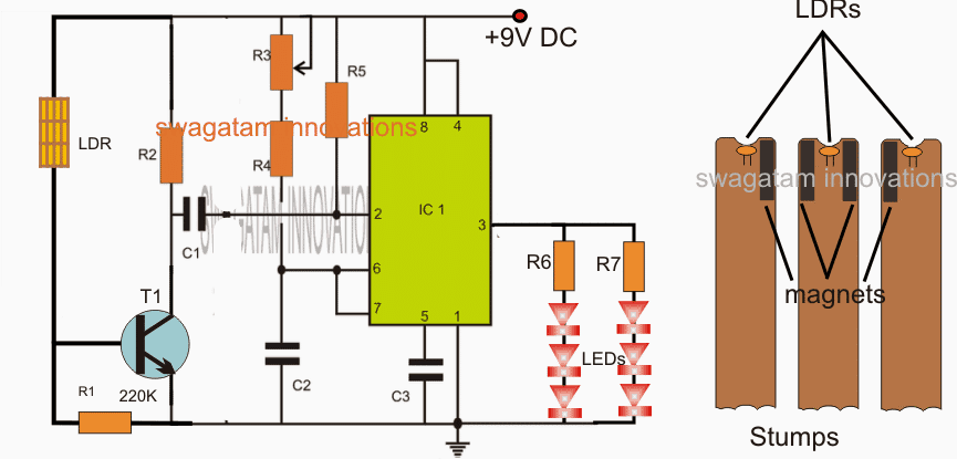
In the diagram we are able to witness the integration methods of the LDRs with a 555 IC based monostable.
As long as the bails are held over the stumps, the ambient light stay blocked from the LDRs which keeps T1 switched OFF. but the moment the bails are thrown of the stumps, the LDRs become exposed to the ambient light enabling T1 to receive a biasing voltage which in turn triggers the monostable so that the LEDs are illuminated for the set period of time fixed by the relevant components.
The LEDs shut of after the set time has elapsed until the bails are restored over the stumps for yet another cycle.
Designed by: Swagatam.
Parts List for the above explained LED cricket stump circuit
- R1 = 220K
- R2, R4, R5 = 10k
- R6, R7 = 220 ohms
- R3 = 1M preset
- C1 = 1uF/25V
- C2 = 100uF/16V
- C3 = 0.01uF
- T1 = BC547
- IC1 = NE555
If you have any doubts regarding the working or the manufacturing of the circuit, please feel free to contact me through comments, will be happy to help!


Questions & Answers
Nice work is what you always keep doing and that's good of you……..Anyway good day sir, I have a problem and what your help, I have been given an inverter circuit diagram by my lecture to build as my final year project and i have been able to find most of the components but there are two remaining ICs am not getting and hoping if you will show me an alternative or if possible universal ICs for them……… LM741 and CNY17… THANH YOU.
thanks! you can use any equivalent opamp in place of the IC 741 such LM301, 318, 709, ca3130, ca3140, LF355/356/357, TL071/081 etc and for the CNY17 you can use any 4 pin optocoupler such as 4N35 etc
thank you very much for your quick response…
Hi dear Sir,
Really Nice circuit. When I see this circuit in your blog I compared the stump price with our indian currancy it takes around 25 lakh but you show that circuit in very easy way whose cost very less nearly equal to not more than 400Rs.
But Some question arise in my mind after watching Ireland And UAE Match in that match The Ball Just Touches stump and Suddenly LED Inside Stump And Bails Glow but due to Bails not Falls down from stump the batsman not given Out.My Question is that is this your circuit gives that Kind Of Accuracy Like that Acuracy Used In International Match Now Days.Sorry for Bad English
Thanks Regards.
Thanks Swapnil,
the bails should never light up just with mere vibration or brushing of the ball, it should illuminate only if it's truly dislodged from the stump slots, otherwise the whole purpose of the system would fail.
The circuit above takes care of this criterion and thus produces a failproof indication for the same.
however the reaction time of the above circuit would be in microseconds.
Sir,
What needs to be done to avoid the LEDs from blinking??
Does the above reduce the complications in the circuit??
Then what will be the new circuit diagram for the above??
Hope you will reply..
Thank You
Vishnu, in the above design the LEDs will never blink, they are supposed to light up for a few seconds and then shut off
Is there any casing or bails you can buy to place the circuity inside?
You will have to fabricate it using plastic molding technique or wood working
Thanks for such helpful article …would you please upload your video of making LED stumps??
You are welcome, if time permits I'll surely do it and post it in youtube.
can you make this circuit with LED flashing?
if you include a 555 astable with pin3 of the existing IC 555…the LeDs can be made to falsh…
I made this but battery drain so fast. can we use arduino tiny85 chip for this.? i have suggestion. we can include transmitter on this bail and trigger stump too. i have design arduino.
use 7(555) IC instead of 555, it'll last much long.
using arduino or wireless circuit will make this simple design unnecessarily complex and beyond the reach of ordinary hobbyist, so I don't recommended that.
the idea here is to produce a simple, cheap and effective version using ordinary parts.
i have made these wickets by own beautifuly but now i wanted to make these LED stumps plz help me in a proper simple way to make proper LED stumps plz
this is the dream of mine to have these LED stumps because i love cricket and i play too much i have made stumps by own and colour it beautifully but now i want to make LED stumps plz help me in a simple common way to make a proper LED stumps plz plz
the design presented above is perhaps the simplest one, and can be implemented with ease, if you have specific questions you can feel free you ask them
can u upload its simulation on proteus?
Sir I'm interested in making led stumps you described above. what are the essential parts needed to make it easily in wooden stumps? Hope you will reply soon.
Sagar, everything's explained in the article, please read it carefully click on the diagram to enlarge
first make the circuit on table for confirming….
the above circuit should be placed in stumps or bails??? I'm confused. please help. can you send me the link of making your led stumps video.. it will be a great help.
it's explained in the article, may be you did not read it properly.
the first circuit is for the bails, the second circuit is for the stumps.
Hello, i am confuse in the operation of reed switch help me out,as we know when we take magnet near reed switch circuit becomes close current can pass and led blink, but in this case magnet is always in top of stump so led always blink because magnet is near reed switch and crcuit close so current flow. Please help me out.
Hello, in this circuit as long as the reed remains closed, the transistor stays disabled which keeps the circuit also disabled, but when the reed opens the transistor triggers and activates the circuit and the LEDs
Thanks for reply,
I have another question, here capacitor 1= 0.22 micro farad
Capacitor 3= 0.01 micro farad in this case please specify the voltage as specify in capacitor 2. Because there are so many types of capacitor available with same rating .
All capacitors are standard type and does not require to be specified, just give the dealer the "uF" values and tell him it's for a 9V battery operated circuit and he will understand what to give.
Sir I am interested in making these stumps.
Can you please explain again that how to make LEDs flash/blink.
I will be really thankful
Hi Haseeb, the simplest idea would be to replace the red LEDs with the RGB flashing LEDs which do not require any external circuit to blink rather automatically change color and blink when connected with a supply source.
Thanku so much sir for a very quick reply.
I have one more question, what changes will be in the circuit if we want to light up a 12v led strip (stumps circuit).
you can remove and replace the resistor from the strips with a calculated one and use it with the recommended 9V supply.
Old R/New R = 12/9….use this formula for the new resistance
What is the easiest way to make the actual stumps light-up, not just the bails
First you should make your very own stumps with pvc pipe. Then you should use red coloured led strips. Which is easily available on ebay or any colour you kinda desire. Then use the very same circuit and for the t1 you can make a small hole about 2 cm kinda thing in the 3 of the stumps. And that’s it doesn’t it sounds pretty simple.
What is meaning of R2,R4,R5=10K , R6,R7=220ohms ,R3=1M preset
What if More leds in bails instead of two
it’s possible if rechargeable battery is used
Can you please make a video on how to insert this circuit in bails and the stumps?
Or anyone who has made this, post a how to, or the end result? Surprised no one has bothered yet…
These are just kinda variables. For eg in maths we use x=5, y=1.ah something like that. There is no need to confuse.
Has anyone made these and has a picture of them? I am interested in how easy it is to fit all the components into the bail.
There are hardly any parts in the circuit, the preset can be eliminated by replacing with fixed resistors…It will easily fit because a hollow plastic bail will have more than sufficient space to accommodate the parts, especially if the parts are SMD
And the stumps turn on at different times, or do they all turn on at once?
the moment bails are dislodged, the stump LDRs get exposed to light, activating the stump LEDs, so it will be almost instantly
But given that each stump has its own circuit, the stumps light up at different times to each ohter?
yes that’s right, the stump lights are synchronized with their respective bails, not with each other, so unless the bails are dislodged the particular stump will not light up,
And what are the specifictions for the reed switches
any suitable type that will easily fit inside the arms of the bails, the smallest one can be as small as this
https://www.electronicspecifier.com/cms/images/large/KSK.jpg
Could you create one circuit for all the stumps, with 3 LDRs (instead of one) in parallel and 6 LEDs (instead of 2), so that when one LDR is activated, the circuit lights up all 6 LEDS in all 3 stumps?
Admittedly, it is not perfect as the stumps would light up when the bail wasnt fully dislodged, but if I am fine with that, would the circuit still work as I say it would?
that looks difficult because the stumps cannot be interlinked through easy means, we have to find a way through which the 3 stumps could be interlinked with their sensors connected in series so if one is triggered all get triggered…but this looks difficult with the present configuration..
I am aiming to make this in a set of plastic stumps so linking the stumps together shouldnt be a problem as I have the plastic base to work with. I have limited experience with LDRs but wouldn’t they be in parallel, so that when one is activated the circuit is activated?If they were in series all would have to be activated to finish circuit. As I said i have limited experience with LDRs so I may be wrong
OK, in that case you can connect the LDRs in parallel, and also make sure the LEDs are connected in parallel with a single IC 555 circuit output.
I mentioned series connection with reference to reed switches, my plan was to connect reed switches for all the stumps in series and make sure the LED circuit stays deactivated as long as the reeds were held closed with magnets embedded inside bail arms, and if any one reed was triggered it would break the link and activate all the 3 stump LEDs…
However the LDR option looks more easy to implement….
Hey,
In one comment, you mentioned that the light will stay lit only for some time, instead of blinking for 5-10 secs as we see it in matches. Is there any method in which we can make it blink as we see it in matches?
yes it may be possible by integrating an IC 555 based astable at pin#3 of the above shown IC 555 monostables, however the whole circuit may get a little bulky, therefore a BJT version would be more suitable here, if possible I may try to update it soon.
Will this set be durable enough to take the blows of atleast a tennis ball? If not, how can it be made durable?
If SMD is used then it will easily withstand any kind of blows
How to do earthing in the circuit? And what about negative terminal of battery? And is connection between R4, C1, C2 and 2 of ne555 a 4 point joint? Please reply sir.
Earthing is not required, the earth symbol signifies the DC negative line. R4 is not connected with C1, it is connected with C2 line
sir, can we use Vibration switch than Reeds Switch. because practically, in Gali Cricket put the magnet in stump is not possible.
Hi Akhilesh, Yes it can be done, I’ll update the new diagram soon!
How to connect capacitor terminal in circuit
Means where is positive & negative connection
The white color is the positive terminal, black is the negative
The circuit is not working as u have given the diagram
It will work 100% if it is made correctly, there’s no way it can’t work
Sir,
Please send me your contact details..I need to make this circuit.
Ramesh, you can express your thoughts here, I’ll try my best to help you!!
Thanks for the useful information 🙂
Hi.. I want to make commercial LED stumps, need your support.
Please provide more details regarding the required specs of your design.
Hi Swagatam, I’m haveing a platform where I can have great potential in manufacturing and sales of LED cricket stumps, if you can prepare a full electric kit and send us for proto trials, we will fix your designed kit in standard size stumps. It may be fiber/acrealic/wooden.
Hi Bhavesh, I wish I could do it but sorry it won’t possible for me to create a manufacturing sample due to work pressure.
can we use ferite magnets instead of neodymium?? will it works fine?
Yes, it should still work, provided it is able to keep the reed switches activated.
Hi sir!
I want to make these stumps but I am not an electronic engineer. Please can you upload a video of how to make these stumps (with full explanation)
I know it will be hard but please try to make.
Hi Muhammad, If you are not an electronic engineer then you must take the help of an engineer during practical assembly, because this project is strictly for people who are well versed with electronics.
Can we use both vibration switch ans reed switch
What as aproximate price of this circut of bails and stumps
0.5 $ without cover and battery
Can you please advise a part number / spe’ of the LDR’s Thanks for your help.
LDR can be small 5mm diameter type, as shown in the following figure:
https://www.homemade-circuits.com/wp-content/uploads/2017/05/LDR-Resistor.png
Hi! Can you please advise me how I can add buzzer to the Vibration Switch diagram?
Hi, you cannot add a buzzer to the vibration switch, you can add it parallel to the LEDs.
Thank you very much for your quick reply. You website is very interesting and useful.
Respectfully,
Jorge
Thank you for your feedback, The pleasure is all mine!
Hi Swagatam!!!
Do you have a vibration switch diagram on the LMC555 chip?
I would be very grateful to you. Thank you.
Hi Jorge, you can easily modify a 555 monostable to work with a vibration switch and produce momentary LED ON in response to a vibrational force.
Here’s the diagram:
Please publish a pcb print of this design which corresponds to Bails and wicket
If time permits I will try…
Would be grateful to you if you take some time to design pcb which will be wicket and bails