A relatively simple 1000 watt pure sine wave inverter circuit is explained here using a signal amplifier and a power transformer.
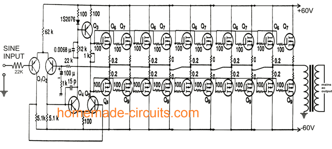
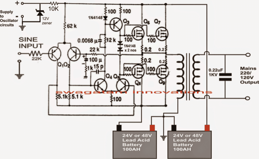
As can be seen in the first diagram below, the configuration is a simple mosfet based designed for amplifying current at +/-60 volts such that the connected transformer corresponds to generate the required 1kva output.
UPDATE:
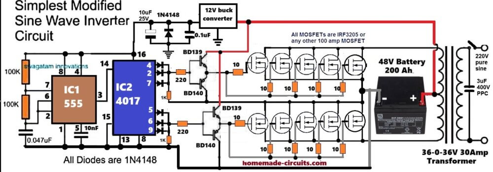
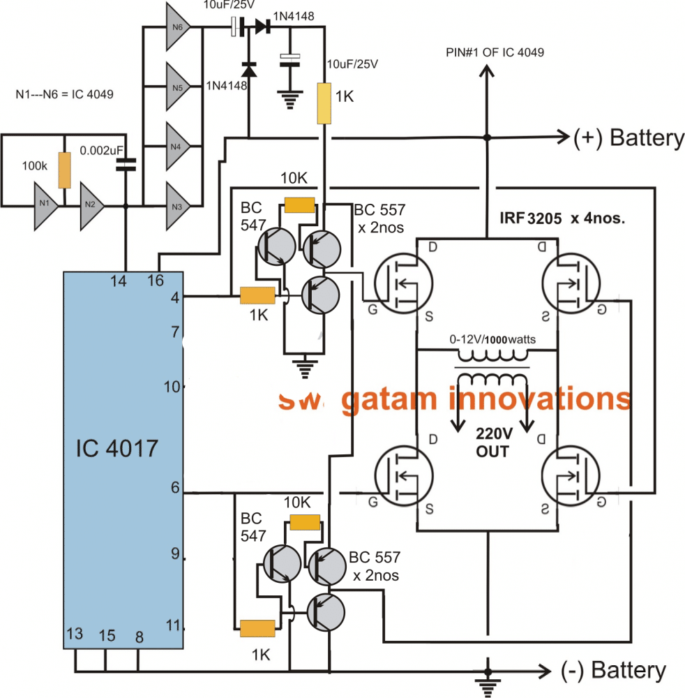
There's a much easier and efficient way of making a 1 kva inverter circuit using the following 4017 PWM version circuit. Since the PWM is created directly through the 4017 output, the PWMs are much accurate and the waveform is uniform and does not depend on any external adjustments.
The biggest advantage of using this circuit is that the output can be modified to almost a pure sine wave by adding a few PPC capacitors across the transformer output.
Here' the circuit which you can try:
Audio/Video Representation
Parts List
- Resistors
- All resistors are 1/4 watt 5% unless specified
- 100K = 2nos
- 100 ohm 1 watt = 1no
- 1K = 2no
- 10 ohm = 2no
- Capacitors
- 0.047uF ceramic or PPC = 1no
- 10nF ceramic or PPC = 1no
- 10uF/25V Electrolytic = 1no
- Semiconductors
- 1N4148 diodes = 7nos
- 12V/1 watt zener diode = 1no
- IRF3205 MOSFETs = 10nos
- Transformer 12-0-12V/220V/1kva
- Battery = 24V/500 Ah = 1no
The previous original article which is continued in the following paragraphs also discusses a 1000 watt inverter circuit, however, this circuit being a linear amplifier is not so efficient, and may result in a lot of dissipation.
I would recommend trying the above circuit, which will give you a 100% results quickly.
Remember, you must first try and confirm the working of the inverter using single MOSFETs on each channel. Once the working is confirmed then you can add more number of MOSFETs in parallel to upgrade the power capacity of the inverter to 1000 watts
Circuit Operation
Q1, Q2 forms the initial differential amplifier stage which appropriately raises the 1vpp sine signal at its input to a level which becomes suitable for initiating the driver stage made up of Q3, Q4, Q5.
This stage further raises the voltage such that it becomes sufficient for driving the mosfets.
The mosfets are also formed in the push pull format, which effectively shuffles the entire 60 volts across the transformer windings 50 times per second such that the output of the transformer generates the intended 1000 watts AC at the mains level.
Each pair is responsible for handling 100 watts of output, together all the 10 pairs dump 1000 watts into the transformer.
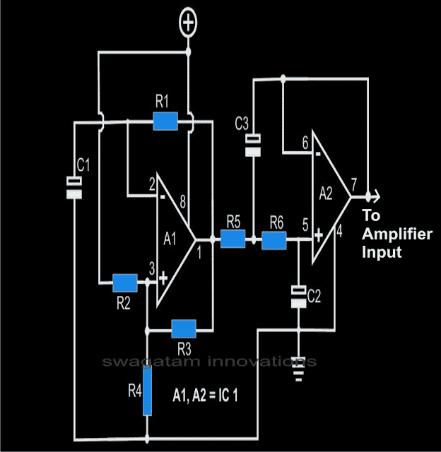
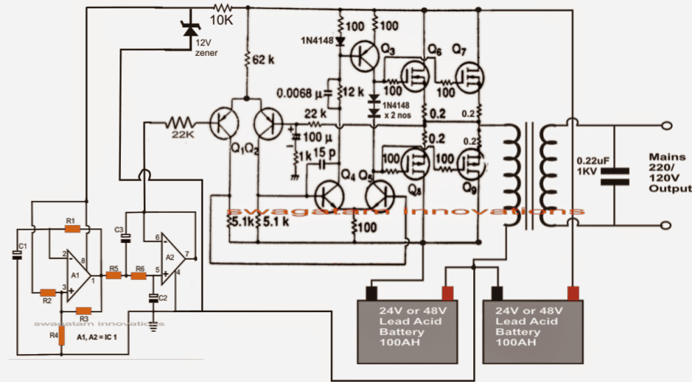
For acquiring the intended pure sine wave output, a suitable sine input is required which is fulfilled with the help of a simple sine wave generator circuit.
It is made up of a couple of opamps and a few other passive parts. It must be operated with voltages between 5 and 12. This voltage should be suitably derived from one of the batteries which are being incorporated for driving the inverter circuit.
The inverter is driven with voltages of +/-60 volts that amounts to 120 V DC.
This huge voltage level is obtained by putting 10 nos. of 12 volt batteries in series.
The Sinewave Generator Circuit
The below given diagram shows a simple sine wave generator circuit which may be used for driving the above inverter circuit, however since the output from this generator is exponential by nature, might cause a lot of heating of the mosfets.
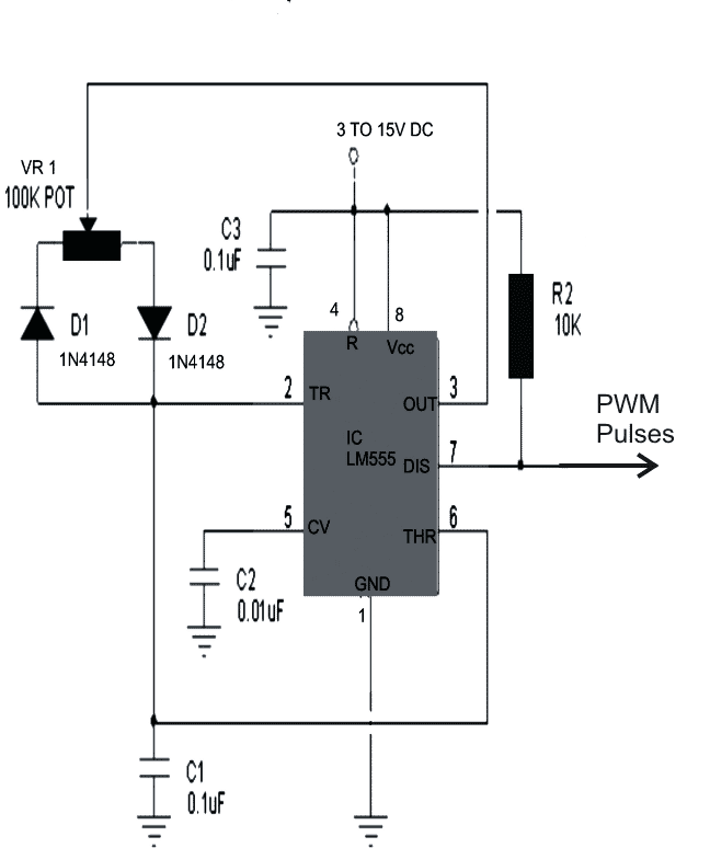
A better option would be to incorporate a PWM based circuit which would supply the above circuit with appropriately optimized PWM pulses equivalent to a standard sine signal.
The PWM circuit utilizing the IC555 has also been referred in the next diagram, which may be used for triggering the above 1000 watt inverter circuit.
Parts List for the sine generator circuit
All resistors are 1/8 watts, 1%, MFR
R1 = 14K3 (12K1 for 60Hz),
R2, R3, R4, R7, R8 = 1K,
R5, R6 = 2K2 (1K9 for 60Hz),
R9 = 20K
C1, C2 = 1µF, TANT.
C3 = 2µF, TANT (TWO 1µF IN PARALLEL)
C4, C6, C7 = 2µ2/25V,
C5 = 100µ/50v,
C8 = 22µF/25V
A1, A2 = TL 072
Part List for Inverter
Q1, Q2 = BC556
Q3 = BD140
Q4, Q5 = BD139
All N-channel mosfet are = K1058
All P-channel mosfets are = J162
Transformer = 0-60V/1000 watts/output 110/220volts 50Hz/60Hz
The proposed 1 kva inverter discussed in the above sections can be much streamlined and reduced in size as given in the following design:
How to Connect Batteries
The diagram also shows the method of connecting the battery, and the supply connections for the sine wave or the PWM oscillator stages.
Here just four mosfets have been used which could be IRF4905 for the p-channel, and IRF2907 for n-channel.
Complete 1 kva inverter circuit design with 50 Hz sine oscillator
In the above section we have learned a full bridge design in which two batteries are involved for accomplishing the required 1kva output. Now let's investigate how a full bridge design could be constructed using 4 N channel mosfet and using a single battery.
The following section shows how a full-bridge 1 KVA inverter circuit can be built using, without incorporating complicated high side driver networks or chips.
Using Arduino
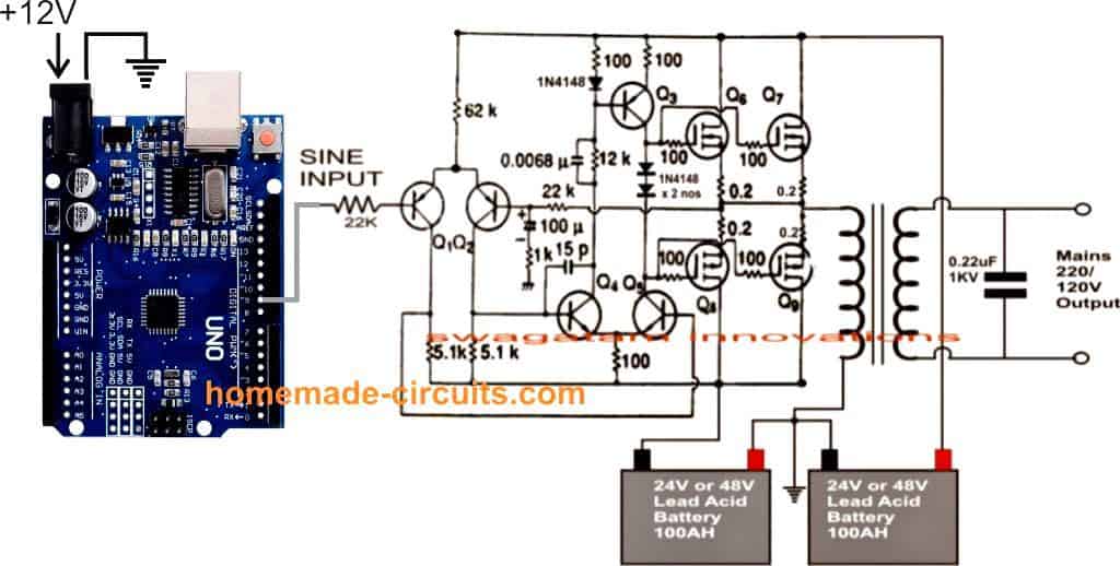
The above explained 1kva sinewave inverter circuit can be also driven through an Arduino for achieving almost a prefect sinewave output.
The complete Arduino based circuit diagram can be seen below:
Program Code is given below:
//code modified for improvement from http://forum.arduino.cc/index.php?topic=8563.0

//connect pin 9 -> 10k Ohm + (series with)100nF ceramic cap -> GND, tap the sinewave signal from the point at between the resistor and cap.

float wav1[3];//0 frequency, 1 unscaled amplitude, 2 is final amplitude

int average;

const int Pin = 9;

float time;

float percentage;

float templitude;

float offset = 2.5; // default value 2.5 volt as operating range voltage is 0~5V

float minOutputScale = 0.0;

float maxOutputScale = 5.0;

const int resolution = 1; //this determines the update speed. A lower number means a higher refresh rate.

const float pi = 3.14159;

void setup() {

wav1[0] = 50; //frequency of the sine wave

wav1[1] = 2.5; // 0V - 2.5V amplitude (Max amplitude + offset) value must not exceed the "maxOutputScale"

TCCR1B = TCCR1B & 0b11111000 | 1;//set timer 1B (pin 9) to 31250khz

pinMode(Pin, OUTPUT);

//Serial.begin(115200);//this is for debugging

}

void loop() {

time = micros()% 1000000;

percentage = time / 1000000;

templitude = sin(((percentage) * wav1[0]) * 2 * pi);

wav1[2] = (templitude * wav1[1]) + offset; //shift the origin of sinewave with offset.

average = mapf(wav1[2],minOutputScale,maxOutputScale,0,255);

analogWrite(9, average);//set output "voltage"

delayMicroseconds(resolution);//this is to give the micro time to set the "voltage"

}

// function to map float number with integer scale - courtesy of other developers.

long mapf(float x, float in_min, float in_max, long out_min, long out_max)

{

return (x - in_min) * (out_max - out_min) / (in_max - in_min) + out_min;

}
The Full-Bridge Inverter Concept
Driving a full bridge mosfet network having 4 N-channel mosfets is never easy, rather it calls for reasonably complex circuitry involving complex high side driver networks.
If you study the following circuit which has been developed by me, you will discover that after all it's not that difficult to design such networks and can be done even with ordinary components.
We will study the concept with the help of the shown circuit diagram which is in the form of a modified 1 kva inverter circuit employing 4 N-channel mosfets.
As we all know, when 4 N-channel mosfets are involved in an H-bridge network, a bootstrapping network becomes imperative for driving the high side or the upper two mosfets whose drains are connected to the high side or the battery (+) or the positive of the given supply.
In the proposed design, the bootstrapping network is formed with the help of six NOT gates and a few other passive components.
The output of the NOT gates which are configured as buffers generate voltage twice that of the supply range, meaning if the supply is 12V, the NOT gate outputs generate around 22V.
This stepped up voltage is applied to the gates of the high side mosfets via the emitter pinouts of two respective NPN transistors.
Since these transistors must be switched in such a way that diagonally opposite mosfets conduct at a time while the the diagonally paired mosfets at the two arms of the bridge conduct alternately.
This function is effectively handled by the sequential output high generator IC 4017, which is technically called Johnson divide by 10 counter/divider IC.
The Bootstrapping Network
The driving frequency for the above IC is derived from the bootstrapping network itself just to avoid the need of an external oscillator stage.
The frequency of the bootstrapping network should be adjusted such that the output frequency of the transformer gets optimized to the required degree of 50 or 60 Hz, as per the required specs.
While sequencing, the outputs of the IC 4017 trigger the connected mosfets appropriately producing the required push-pull effect on the attached transformer winding which activates the inverter functioning.
The PNP transistor which can be witnessed attached with the NPN transistors make sure that the gate capacitance of the mosfets are effectively discharged in the course of the action for enabling efficient functioning of the entire system.
The pinout connections to the mosfets can be altered and changed as per individual preferences, this might also require the involvement of the reset pin#15 connection.
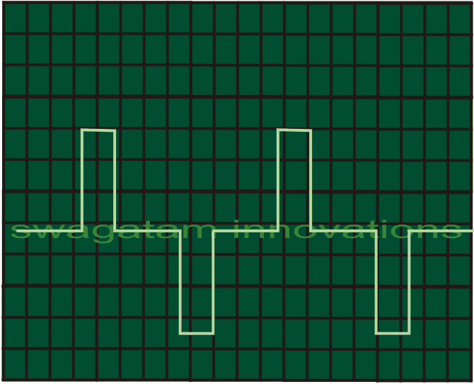
Waveform Images
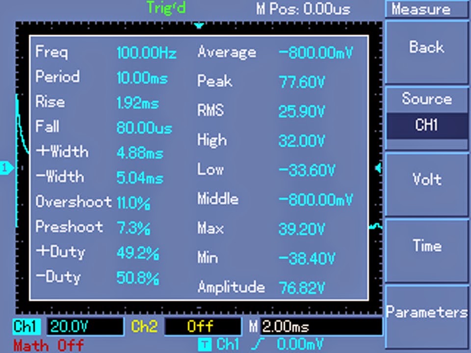
The above design was tested and verified by Mr. Robin Peter one of the avid hobbyists and contributor to this blog, the following waveform images were recorded by him during the testing process.




Questions & Answers
To make an UPS you will need to make a inverter first, so you can begin with the above circuit, once you finish this I'll help you to proceed with the further things.
The above circuit will work with 12V supply also, but with 12V supply a 1000 watt inverter will become too heavy with thick wires and huge heatsinks, that's why higher voltage is recommended.
Hi Kabir,
50 watt panel is too low to power an inverter directly, you will need at least a 100 watt solar panel for this.
You can try a simple inverter circuit that's explained in the following article:
https://www.homemade-circuits.com/2012/09/mini-50-watt-mosfet-inverter-circuit.html
That won't be enough, you will need a minimum 200 watt panel for charging a 200 AH battery within 6 hours, please confirm it further with your panel dealer
If possible I'll try to design it and post it for you soon
hey, please i would like to know the function of the function of c2 in the 555 pwm circuit. I need to connect a comparator to the 555 timer circuit for my switching supply
C2 is for keeping pin#5 unresponsive to stray noise and disturbance that may be present in the supply and atmosphere
Hi, I'm building a hydro, as a generator I'm using truck alternator 24V 100A, could I use the above design inclusive PWM, and also what would I have to change in order to double its output to 2kV ?
Thank you for your reply. Ladia
Yes you can use it.
You can increasing the input voltage and the trafo primary voltage appropriately for increasing the output wattage to the desired levels, without increasing mosfets nos.
Mr swagatam thank you for the good job sir i want to build this circuit named Make This 1KVA (1000 watts) Pure Sine Wave Inverter Circuit to power my house so please help me build it my 1th question im going for the LM555 where is that point show 3 to 15v dc from pin 4 of the ic lm555 going to connect second question in the TL072 A1,A2 where is the point show plus symbol from pin8 of the A1 connect and A2 pin7.can i use one of this mosfets IRFP250 IRFP260 AND 2N3205 OR 2N3055 please sir kindly help me cos we having a lots of problem in our electricity thank you i am looking forward to hear from you son.
Hi Stev,
you will need two 12V bats connected in series for operating the above inverter. Meaning together the battery will generate 24V
The series connection will become the ground (earth symbol) of the system.
For the IC 555, the positive of the battery which generates 24V will become its positive supply while the series link of the batts will become the ground of the circuit, same can be done for the A1/A2 circuit if it's being used in place of the 555.
This also means that the earth or the ground of all the circuits can be made into a common line.
pin7 of A2 will connect with the inverter input.
than you sir for the respond but sir there is one thing i don't understand in the mosfet you named some of the mosfet Q6,Q7,and Q9,Q9,please which of them are the N-channel mosfet K1058) and P-channel mosfets J162) in the Make This 1KVA (1000 watts) Pure Sine Wave Inverter Circuit,thank you stay bless looking forward to hear from you.
I just cut/pasted the first mosfet section across for indicating the following identical moset stages, that's why it's showing a repetition of the same mosfet, please ignore it, and simply repeat all the section identically with 0.22 resistors on each and every mosfet source
thank you for the replied but sir i still don't get you right can you please come again or you mean all the 20 mosfets should be the same mosfets? and also the diode (1s207) i never head that kind of that diode before any diode can be use or what is the value of it? thank you looking forward to hear from you stay bless.
all the upper n-mosfets are same and all the lower p-mosfets are same.
you can use 1N4148 diode in place of the shown unknown diode.
ok sir thank you very much for the respond sir i build it but it dont work why sir is there anything i did not connected? ok let me tell you how i connect the circuit, in the 555 there is line that from it 7pin show (PWM pulses) i connected it with A1 pin8 that show positive symbol to the Btr positive im i right? and also i connected pin7 of A2 to the sine input sir in the 555 you connect pin4 and 8 together and you show 3 to 15v DC where is that going to? thank you sir for your time on me.i am waiting for you reply before i will continue the circuit Make This 1KVA (1000 watts) Pure Sine Wave Inverter Circuit.
There are many things that must be taken care of here. The circuit will require a dual battery supply, example 2nos 24V batts in series. the series connection will become the ground.
the preset will need to be adjusted correctly or alternatively it can be simply replaced with two series connected 1N4148 diodes, anode up, cathode down.
try with the 555 circuit first and using just two mosfets
sir im very confused why becos in the parts list there is C4,C6,C7,C5,and C8 while its not in the circuit i can only see C1, C2, and C3 in the op am TL072 sir im talking about this circuit Make This 1KVA (1000 watts) Pure Sine Wave Inverter Circuit here are the parts list
All resistors are 1/8 watts, 1%, MFR
R1 = 14K3 (12K1 for 60Hz),
R2, R3, R4, R7, R8 = 1K,
R5, R6 = 2K2 (1K9 for 60Hz),
R9 = 20K
C1, C2 = 1µF, TANT.
C3 = 2µF, TANT (TWO 1µF IN PARALLEL)
C4, C6, C7 = 2µ2/25V,
C5 = 100µ/50v,
C8 = 22µF/25V
A1, A2 = TL 072
Part List for Inverter
Q1, Q2 = BC556
Q3 = BD140
Q4, Q5 = BD139
All N-channel mosfet are = K1058
All P-channel mosfets are = J162
Transformer = 60-0-60V/1000 watts/output 110/220volts 50Hz/60Hz
zinnaboy, please follow the diagram only, I might have put the parts list of "simple sine wave inverter" which is quite similar to the above design.
So please follow the diagram only.
thank you sir for the humble replied cos some time we asked questions that almost make you upset but becos of the sacrificed you ignore and answer thank. so if i understand well the out put of 555 and out put of A1/A2 should connect to the inverter in put right?
yes that's correct, but make sure you do the connections as instructed in the previous comment.
hi sir i build this circuit Make This 1KVA (1000 watts) Pure Sine Wave Inverter Circuit but the fets got hots without load please help me solve the problem thank you sir
Hi Bianz, connect small flashlight lamps in series with positive and the negative lines of the circuit…these lamps should be rated at the battery voltage level.
now without connecting any load switch ON power to the circuit.
The flashlights will light up brightly, now carefully adjust the preset until the lights just shut off. This setting will ensure that your mosfets stay cool when there's no load.
thank sir but one thing is that when i switch on the power to the circuit the 0.22 ohms resister blow i used only 2 fets (K1058),(J162) for trying before i go ahead and build bigger one please i need your help sir.
biannz, keep the trafo wire disconnected initially, and connect it after power switch ON, if still it the 0.22 blows off means there's something seriously wrong with your circuit.
hi Sawagatam, I am new here but you seem to be in the know. I have some 250volt 250watt solar pannels and some 30 12 volt 240ah batteries, I want to make a transformerless inverter, do you have any sugestions for me? like battery pack voltage. I was thinking of about 216vdc before switching as I know that this will affect the ac voltage.
Hi Simon, you will need a full-bridge inverter (without transformer) circuit for implementing the application.
I'll be publishing one such circuit soon in this blog, in the meantime you can search it online to get a idea about the design.
The batteries can be connected in series for getting the required 216V.
sir thank you sir i did it a exactly as you said but still blowing the fest and the resistor it happening to one side i used 2 most fest N-channel mosfet K1058
channel mosfets J162 , sir in the inverter i use 18pf in place of 15pf,and the resistors i used 5.6 in place of 5.1 cos it not aveable here im asking sir is it the cost of problem? sir i will be very glad if will be able to build this circuit so please sir help me sir thank you i hope to hear from you son.
biannz, the preset needs to set correctly first….alternatively you can replace the shown preset with two 1N4148 diodes back to back in series. anodes will be upwards and cathodes will be downwards…..
hi sir i understand but want to ask you a little question where is the 1k resistor which indicate ground connect to is it connect to the positive and negative center of th batt or directly to the negative of the batt which generate 24v? thank you your assistant.
hi biannz, pls see the last diagram, i have shown how to connect the batteries and the supply connections for the oscillator circuit
ok thank you sir but one thing is how can i post or upload so that you can see pics can you give me your email address if you don't mind? i prefer to chart with you live but i don't think that would be possible thank you sir.
you can use Google drive and create a image link through it and provide me with the link.
sir please can i use two 12v batt in series for test?
yes can be used but it will give 50% less power
ok sir please i sent you some pics to this email homemadecircuits@gmail.com please check and correct it if any wrong connection.
March 24, 2014 at 3:41 PM
bianzz, i cannot check your circuit due to lack of time…you will have to do it yourself.
You should first make it on a general purpose board going for a PCB
…..than compared to two 24V batteries
sir please i have sent you a pic of the three circuit i have connect all so please kindly check it out if it correct or not im waiting for your reply sir thank you.homemadecircuits@gmail.com
The connections are wrong.
do it exactly as shown in the last diagram above.
Use only one pwm circuit out of the two which are shown, either the one which uses the two opamps or the the one with 555 IC.
sir so you mean only two circuit should be connect not all the three circuit,i should chose any of them to connect the inverter isn't it sir? i have sapirate them see the connection if not please correct it and send it to this email address(
danieladusie@gmail.com) this is the email address that i sent to(homemadecircuits@gmail.com)
biannz, please see the last design in the above article.
thank you sir so can i use the one with ne555 too if want? i mean can i chose one of the two circuit to feed the sine input any of them with the same connection?
Yes you can use 555 pwm input also, connect it in the same manner as done for opamp oscillator
ok sir thank you for respond,sir please i want to know if this circuit can handle or supply 5 BIRD ROM with one LCD flat-mar TV one refrigerator 5 ceiling fans and two computers? sir i want to use 4 12v solar the bigger and 0-48 Tranf and also good heat sink for the fets,sir if you confirm that this circuit
Complete 1 kva inverter circuit design with 50 Hz sine oscillator can handle the house then i use solar panall instead of electricity to charge the BTT,thank you sir.
Biannz, according to me the above design will be able to handle the specified appliances….however I cannot provide guarantee for anything.
Better to build a smaller version by using two mosfets, two 12V 7.5 ah batts, if everything goes right as per the expectations, you can proceed by upgrading the stages appropriately.
ok sir i understand you very well it a good i dear i will do exactly as you said.
sir please i need your help i finish build this circuit but unfortunately i did not gets 0.2E so i used 0.22E the problem is when i connect the 0.22E and the fets got very hot and it almost burn.
biannz, remove the sine oscillator input, and short circuit the inverter input to ground and then check whether the mosfets are getting hot or not.
If yes, then there could be something not correct with the connections.
0.22 ohms is OK.
sir thank you sir please i did as you said but it still got hot sir i build the circuit as the way it is i go over and over i check every the circuit i connect everything where it should connected so sir my observation i didn't miss the connection so please help me
without an input signal the fets will never heat up, i have the tested the design and it worked perfectly for me.
you circuit has some fault for sure get it checked by a expert.
i had cautioned you before not to try something which you cannot troubleshoot yourself.
sir i use Proteus and tell me IRF2907 have no model specified,simulation failed due to partition analysis error(s) sir tha is how it tell me so what does that mean? any help?
biannz, for simulation purpose you can use any n-channel and p-channel mosfets in the circuit.
sir please in this circuit it Q8 AND Q9 N-channel or P-channel?
P-channel
Hi Swagatam
Recently, the transformer of my UPS (purchased from market 3 years ago) is becoming very hot, such that strong smell can be felt in the room.
What could be the reason?
Hi Abu-Hafss,
May be it incorporates some kind of voltage regulation circuitry which has failed now and as a result excessive voltage and current is being fed to the transformer input winding.
Transformer = 60-0-60V/1000 watts/output 110/220volts 50Hz/60Hz
what do mean 60-0-60?
sorry, it should be 0-60V and not 60-0-60
it's the voltage rating of the primary side winding of the inverter transformer.
how to we can 20 volt dc convert into the ac 220 volt please
you can try the following circuit:
https://www.homemade-circuits.com/2014/06/simple-high-voltage-generator-circuit.html
please lm555 will produce the same sine wave as tlo72 oscillator?
555 will produce pwm modified pure sine wave, A1, A2 will produce exact pure sine wave
sir
i want to try this circuit again but my problem is the 15pf i search every where but i don't get it, it very difficult
daniel, you can try any closer value, it's not so critical
sir please can i use variable resistor to adjust so that i can get 14k3 or 12k1 cos it difficult to get that value can i?
yes you can use presets for adjusting the values
in the parts list you have a "2µ2" value for C4, C6, C7 I cannot find such a value was that a typo?
yes it's a typo from the previous extraction, just remove the Â
ok one more thing the 2uf capacitors which I should put two in parallel are they the big 250v/450v caps found in fans because that's mostly what I see.
No, these are small 25V rated, tantalum types are preferred for their low leakage properties and high accuracy.
if thats correct which voltage caps should I use.
sir
please can i use this TL072 oscillator to connect to another circuit you named it simple pure sine wave? that simple pure sine oscillator also use tl072 but i don't want to use that circuit i prefer this the second oscillator, can i use it for that simple sine wave power stage? thank you.
daniel, yes you can use the PWM version with that circuit input
ok sir thank you im going to try it
sir please i build this oscillator TL072 it work very well i got correct pure sine wave but if i connect it to the inverter the fets and the 0.22 ohm resistor got very hot can you help me with that? i tried to send you the pic but it couldn't go through but i well try again after hearing from you,please don't forget to answer this too,sir please can i use irf540n in place of irf2907? thank you
on what situation are the fets heating up? on power switch ON… without input signal and without load…or under what conditions?? please specify.
ok sir
im trying to troubleshot if i couldn't i well inform you so that you can you can help me,but please answer this for me sir please i want to use this TLO72 oscillate for center tap transformer may be one of your cd4017 circuit i think it have one in put or it can be possible?thank you hope to hear from you.
i did not understand what you are saying….
sir i mean i want to use the tl072 circuit to feed cd4017 circuit so that i can use center tap transformer cos the cd4017 it have one input which is pin 14 the out put is many but we anomaly use pin2 and pin7,you have cd4017 inverter circuit so i want to cut it pmw and use this tl072 sine wave oscillator, can it work? sir please my English is not good so please try to understand what mean thank you.
No, that's not possible! It doesn't work that way.
sir
please i have sent you some wave form of TL072 oscillator check it out if it better cos if i connect to the inverter it dont work one side got very hot almost blow my fets any help sir?, thank you.
Daniel, is the heating happening with loads connected or without loads?
and when the input sinewave input is removed are the mosfets returning to normal temperature?
what rating transformer did you use?
did you check the quiscent current of the circuit.
did you connect the two 1N4148 diodes at the collector of Q3?
yes sir the diode is connected, it got hot without load ,i use IRF540N in place of IRF2907 cos IRF2907 it difficult to get it,or can you please tell me common N-CHANNEL MOSFETS?
daniel, do not connect any input signal, initially keep the input 22k end shorted to ground.
now power the circuit with small 12V flashlight bulbs in series with the battery supply lines (+) and (-).
If the bulbs glow brightly would mean something's wrong with your circuit.
The bulb glow will suggest that the quiescent current is too high for the circuit and it has not been configured correctly.
in a good circuit the bulbs will stay shut off
God day Sir
I would like to ask for your help if you have a 5kw pure sine wave inverter. with an input/output 24Vdc/250Vac 60 hertz design. I'm very much fascinated with your designs. I would highly appreciate it if you could help me with this.
Thanks and best regards.
Radley
Hi Radley, you could probably try the following design, you can try replacing the ferrite core trafo with a standard iron core transformer having 5kva rating
https://www.homemade-circuits.com/2014/07/5kva-ferrite-core-inverter-circuit.html
I'm very much fascinated with your design. I would like to ask for your help if you also have a design for 5kw pure sine wave inverter and an input/output of 24Vdc/250Vac 60hertz. I would highly appreciate it if you share it with me.
Thanks and best regards.
Radley
hi sir long time yes am was very busy,so now am back to the blog th last time i said this circuit got hot you answer me but unfortunately i couldn't do it as you said so now i have a time am going to stat it so i will come for your aid if
sir plse can i use irf540n in place of irf2907? thank you.
yes it can be used.
the transformer used in this circuit has a 60v primary and 110/220 output at about 10amps where can I get such a transformer?
60v or higher trafo is used for minimizing the current requirement of the inverter, you could as well use a 12V trafo with a 12-0-12V batt for the same results, but that would mean the amp rating going up significantly………
Oops forgot to mention in the tricky challenge………it would be far better if a swich for sinewave,squarewave,traingle and sawtooth wave. if not at all possible,make it sinewave alongwith PAM/PWM/PPM controller
Could a 12-012 transformer at 10amp be used and does it mean I could only use a single 12 volt battery
yes a 12-0-12 trafo can be used with a single 12V battery, in fact the trafo could be a 9-0-9v ideally.
In that case look at the connection in the diagram that the positive lead from the battery on the right connected to q7 would that connection still be made using one battery or just the portion with the battery to the left?
I am sorry, ignore the previous comments by me…a center tap trafo and a single battery will not work for the above 1000w inverter concept….
The transformer i have is 12-0-12 i used on 12v battery and i didnt get any out out, the fets got hot in seconds so can i use 2 12v batteries in series and use that same transformer that i have