The proposed long range transmitter circuit really is very steady, harmonic free design which you can use with standard fm frequencies between 88 and 108 MHz.
Technical Specifications of the Transmitter
This will likely encompass 5km spectrum (long range). It includes an extremely consistent oscillator for the reason that you employ LM7809 stabilizer that is a 9V stabilized power source for T1 transistor and for frequency realignment that may be reached by means of the 10K linear potentiometer.
The output strength of this long range rf transmitter is approximately 1W however may be more significant should you use transistors like KT920A, BLY8, 2SC1970, 2SC1971…
Transistor T1 is employed as an oscillator stage to present a small power steady frequency. To fine-tune the freq. apply the 10k linear potentiometer this way: should you moderate, in the direction of ground, the freq. would probably decrease but when you fine-tune it in direction of + it would climb.
Essentially the potentiometer is needed just as a flexible power source for the a pair of BB139 varicap diodes.
Both of these diodes function as a changeable capacitor whilst you regulate the pot. By tweaking the diode capacitance the L1 + diodes circuit renders a resonance circuit for T1.
Feel free to employ transistors similar to BF199, BF214 however be careful not to use BCs. At this point you don’t receive yet the long range fm wireless transmitter due to the fact that the electric power is fairly reduced, a maximum of 0.5 mW.
How it Works
The proposed transmitter circuit works in the following manner:
Always encase the oscillator stage in a metal guard to avoid parasite frequencies destabilizing the oscillating stage.
Transistors T2 and T3 functions as a buffer stage, T2 as a voltage amplifier and T3 as a current amp.
This buffer stage is vital for freq stabilization simply because is a tampon circuit between the oscillator and the preamp and final amplifier. It happens to be renowned that bad transmitter layouts normally change freq. whenever you alter the finalized stage.
Using this T2, T3 stage this won’t occur again!
T4 is a preamplifier stage and is employed as a voltage power rf amplifier which enables it to produce adequate power to the ending T5 transistor stage.
As is demonstrated T4 carries a capacitor trimmer in its collector, this is definitely accustomed to render a resonance circuit designed to drive T4 to promote more advantageous situations and do away with those undesirable harmonics.
L2 and L3 coils has to be at 90 degrees perspective one to another, this is to prevent frequency and parasite coupling.
The concluding stage of the long range rf transmitter is equipped with any rf power transistor containing no less than one watt production power.
Utilize transistors like 2N3866, 2N3553, KT920A, 2N3375, 2SC1970 or 2SC1971 should you wish to produce a professional fm transmitter with ample power to take care of an extended spectrum zone. Should you use 2N2219 you will definitely get a maximum of 400mW.
Make use of an effective heatsink for the T5 transistor because it becomes slightly warm. Make use of a reliable 12V/1Amp balanced supply of power.
How to Set-up the Transmitter
Begin by building the oscillator stage, solder a tiny wire to T1 10pF capacitor out and hearing a fm radio, tweak the 10k pot until it is possible to “hear” a blank disturbances or maybe if you connect an music base you could listen to the melodies.
With a 70cm cord it is possible to take care of a 2 – 3 meter region simply with the oscillator stage.
Next carry on and construct the remaining of the rf transmitter, utilize correct shielding as suggested in the above explanation.
As soon as you have completed the transmitter design, hook up the antenna or more effectively a 50 or 75 Ω resistive load and make use of this as a rf probe, feel free to use 1N4148 diode in place of the probe diode.
Fine-tune yet again the 10k pot to favored freq. thereafter go to T4 stage and scale down the initial collector trimmer for highest voltage signal on the multimeter.
After that carry on with the subsequent trimmer and so forth. After that get back on the very first trimmer and readjust yet again until you receive the maximum voltage on the multimeter.
For one watt rf power you could possibly ascertain a twelve to sixteen Voltage. The method is P (in watt) is equivalent to U2 / Z, wherein Z is 150 for 75Ω resistor or 100 for 50Ω resistor, nevertheless one should keep in mind that the proper rf power is lesser.
After those modification, in case things are heading nicely hook up the antenna, keep on employing the rf probe, readjust once more all of the the trimmers right from T3.
Guarantee you don’t have harmonics, verify the TV and radio set to determine if there exists fluctuations on the band. Verify this in an alternative area, a long way away from the fm transmitter or antenna.
The unit is all set up to be used for exchanging music, talks, chats across the suggested range and bands.
Circuit Diagram
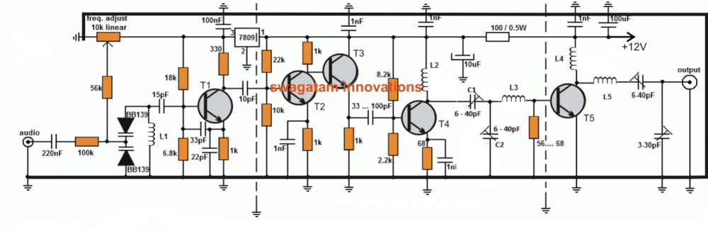
All Inductors are air cored
L1 = 5 wounds / 23 SWG / 4mm silvered copper
L2 = 6 wounds / 21 SWG / 6mm enamelled copper
L3 = 3 wounds / 19 SWG / 7mm silvered copper
L4 = 6 wounds / 19 SWG / 6mm enamelled copper
L5 = 4 wounds / 19 SWG / 7mm silvered copper
T1 = T2 = T3 = T4 = BF199
T5 = 2N3866 for 1Watt / 2SC1971, BLY81,or 2N3553 for 1.5 to 2W power.
Feedback from Mr. Himzo (a dedicated follower of this website)
Hello Swagatam,
I have few questions about your long range fm transmitter.
Firstly about the shielding, what is the most simplest solution to avoid those "parasite frequencies"?
Secondly, what means those 1nF capacitors at the top? Can they be simple in parallel connection or they need to be separated to every transistor like in scheme?
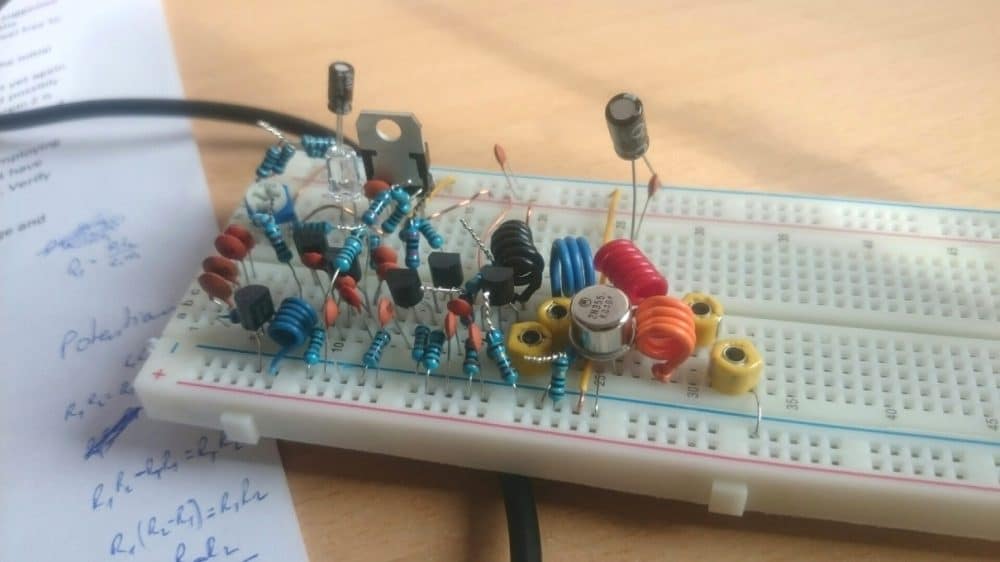
Thirdly, I sent you a photo of transmitter, I didn't turn on amplifier part because my heatsink is coming. Where can I put antenna for testing without amplifier (T5 stage)?
And lastly, how can I modulate those trimmers if I dont have plastic screwdrivers?
Thank you very very much, this is great project.
Your fan, Himzo.
Solving the Circuit Problem
Hello Himzo,
the simplest and the only way to shield the various sensitive stages is by using metal walls between the stages...
the 1nF capacitors should be positioned exactly where these are indicated in the diagram.... the picture which you have shown will never work... transmitter circuits require extreme care as far as their construction and positioning of the components are concerned.
You can never build a long range transmitter successfully on a breadboard, you will have to do it on a well designed PCB which should have a grounded track base layout encompassing all the thinner tracks, only then you can expect the transmitter to work...that too after careful optimization of the trimmers and by employing a compatible antenna.



Questions & Answers
can i use this circuit for transmit my wifi signal within range 5 km ?
do you have any other circuit for transfer/receiver wifi signal in long range ?
No, that won't be feasible because wi-fi signals are not RF based and will require different type of encoding/decoding process.
can you give wifi signal transmitter and receiver circuit diagram for long range like 5 km to 10 km
I don't have any idea regarding wi-fi transmission.
what type of receiver is used for receiving the signals, is it an ordinary FM radio?
In that case you can feed the transmitter audio output to the input of any good 10km range transmitter circuit, the audio then would be transmitted across the specified distance.
have you test this circuit and it is necessary to have the diameter?
Not tested, yes diameter is critical
hello sir iwant this fm transmitar sir so you made this circuit and send me my adress sir plees thanq this product money details send me my mail askmbasha30@gmail.com
I am sorry Basha, it wouldn't be possible for me due to work load.
ok thanq sir iam intrest long range fm transmitar circuit i made it ,so this circuit meterial components and cabinet your buying and send coriear my adress pleese sir ,this circuit price telme i paying your account pleese telme your nomber
Hello Basha, I don't have a PCB for this design, and also I cannot find the transistors in my local shops, so I am also having difficulty in making this unit, in future if I am able to arrange all these I would surely do it for you.
ok thanq sir
With yooir permission i can commercialise the circuit.
permission granted:) …anyway it's not my design.
Dear Swagatam,
I would like to have a receiver for this transmitter for switching purpose, is it possible and logical??
or you advice me to better look for another kind of transmitter. Clarify to me please.
Regards.
hey swagatam, i'm trying to make a transmitter that can send a continuous signal to a receiver i dont have to transmit audio signals can that can be done with your circuit if yes how and what changes i have to make in your circuit to do that. Also can i change frequency of transmitter when its on.and how can i find which frecquncy is currently transmitted by the circuit. please answer my queries.
sorry for my bad english.
Regards
Hi Amol, by continuous signal do you mean a blank signal which will produce a null spot in the receiver? It can be done by not connecting the input to any kind of signal source. keep the input connected to ground and tune the transmitter to get the required null spot in the receiver.
Thanks for the reply Swagatam, acctully i'm trying to make a reciever that collects signal from your transmitter and sends signal or current to base of a transistor and another circuit is connected to emitter and collector of that transistor, so when base gets current the another circuit gets complete.Please he me to make the reciver circuit or is there a better way of doing it.
Hi Amol,
I have discussed one similar application in the following article, you can refer to it:
https://www.homemade-circuits.com/2011/12/how-to-make-fm-remote-control-using-fm.html
the better way is to use the profesional RF modules with encoder decoder chips, but those are within 100 mters range
Thanks Swagatam, firstly my requirement of range is minimum 1 km as it is a aeroplane and also using the professional RF modules with encoder decoder chips need to be programmed and the will affect my budget the engine is ready but I need something to control the flaps.Can you suggest another way. I think that the same thing(Transistor part of my reply) can be achieved with AM technology I have receiver design but not sure that it will work.Please suggest me a AM transmitter design
Hi Amol,
sorry, I don't have an AM transmitter design with me.
Moreover when it's an airplane that you want to control, only FM technology would suit better because AM could be inaccurate and include disturbances in the signal.
RF modules does not require programming, they can be procured readymade but I am not sure about their maximum range, I have never seen a 1km RF remote control device in the market.
Hai, i am from cochin kerala india.i cant get BB139 here. so what. can i add as substitute.pls help me..
Hi, you can use any VHF/UHF varicap diode in place of BB139, the value is not critical.
Try the one which are used in TV tuners.
Is varicap is nessessary or not.becoz am not geting any varicP here local.
can i use anthing substitute of this varicap diode, becoz am not geting any varicap here
I JUST WANT TO KNOW HOW MUCH DISTANCE IT WILL GO THIS TRANSMIT ION, obstacles like trees is a problem or not, become i am going to use in area little like a forest, so is this successful to transmit 1 km ?
No, you cannot substitute the varicap.
trees and structures will not affect the transmission.
helo i bought BB122, i made up to T1 and 10pF capacitor, and as u explained above, i cant hear any blank disturbances in a near by radio, kindly help me
you will need to build upto T4 minimum to make the transmitter work.
tomorrow i would be publishing another similar circuit, but with much easier design, i would suggest you to try that instead of this.
nobody try this, simply wastage of time and money, this circuit wont work.
I made this circuit exactly as diagram.
the circuit is perfect and will work if done correctly as per the given instructions.
HI Swagatam How to Transmit 5km TV RF signal by air ?
Hi baseer, to transmit video signals at long distances will require highly sophisticated circuits, i do not have it presently.
Swagat wher got it BF199 transister in india
Hi Baseer, you can get it from all metro cities in India, Mumbai, Delhi, Kolkata, Bangalore, Chennai, anywhere.
hi all !
it seems a good design and want really to realize it : but can anyone tell us where is the VCC + terminal ? it is not shown on the diagram?
The line which is connected to L4 must be supplied with the positive.
is it possible to use this module as rc plane controller with multiple channel ? i want to make my own long range rc transmitter and receiver…
sorry no, this cannot be used for such complex operations.
you have any simulation of this circuit?FM transmitter is my semester project and bb139 is not available in my city please suggest me any other varectror diod which i can use instead of it.
sorry, no I do not have any simulation for this design. you can try any other equivalent for the shown varactor diode, it's not too critical.
please not that the above circuit may not be so easy for a newcomer, I would recommend you to search for a design which has a PCB layout.
hello swagtam , i need fm radio transmitter circuit which should be simple
sir is this circuit works by antenna???
yes you will need to connect a 50 ohm terminated yagi antenna at the shown output points
I love this design I have made it but not tested yet because I need a receiver that can work for it. please post one to me please its urgent. because this is my final school project.
and how can I make another person talk back to the receiver from another transmitter.
you send to to my mail box at ochar2men@gmail.com
thanks! in the article it's mentioned that the receiver is a FM radio, please read the setting up procedures.
you can use mobliephone fm
yes you can
thanks for your respond but I actually need a seperate receiver circuit instead of the fm radio reciever seperatly. what I actually want to do is incorporate the receiver into the transmitter system as a device for distance learning.
For converting the above design into a long range walkie talkie you can make a small FM radio and use it with the above transmitter circuit but I am not sure how the units would interact while operating on different frequencies..
Good day Engr swagatam.
I dad not seen the position of + line of my power supply.
Good day Adam,
The L4 upper line is where a positive 12V needs to be applied.
L4 has two terminals, one is connected with T5 and the other terminal is connected to the 100 ohms resistor. So i should applied my 12v to the terminal that is connecetd with 100 ohms resistor?
Secondly, i am not understand the symbol of 10 uF capacitor that connected with 100 ohms resistor
12V supply will go to the 100 ohm and L4 junction line.
the 10uF capacitor shows one terminal connected to earth, that's the negative terminal of the capacitor, the lower one, the upper one is connected with the positive line.
Sir, the normal variable capacitor has three terminals, so how can i connect the variable capacitors in this circuit sence the circuit diagram indicates only two terminals.
Secondly, i need more explanation about varicap diodes.
Thanks for this greatful work
for the variable capacitor you can use the center terminal and any one of the other two terminals, the remaining one can be left unused.
varicap diodes change and adjust their capacitance value in response to the varying amplitude of the input frequency providing the most optimal input feed for the preamplifier stage
Engineer Swagatam, I wanted to know what type of microphone should be used alongside this FM transmitter. Thanks for attending my requests.
Hi Adam, you can use any electret condenser mic for the shown circuit
Engineer, I want to know the value of the upper resistor connected to the collector of T1. It is not clear to me. Thanks.
It's 330 ohms
Engineer, I encountered a problem with the FM transmitter circuit. This was because of my system's resolution that I cannot understand the value of the upper resistor connected to collector of T1. It looks like 10k, 15k or 18K. Please, make it more clearer specifically.
Adam, click on the diagram to enlarge it, and you'll be able to see everything distinctly….T1 collector resistor is a 330 ohm resistor…how do you see it as 15k, or 18K??
Hello Engineer thank you for sharing this wonderful project. Please can I use this design to send video signal?
hello lucky, it may be possible, not sure though, just Google "video transmitter circuit" and you'll plenty of good circuits online.
By the way, you can also refer to the following design for the same:
https://www.homemade-circuits.com/2013/10/simple-tv-transmitter-circuit.html
Can I use 2.4ghz for remote
Dear Engineer,
If I want to get 10km Range then what no of transistor should be used in this circuit.
Also suggest what type of antenna is suitable for it ?
Dear Suman,
the range cannot be increased just by changing the transistor, it can be much more complex than this….so it's not that easy.
Hi Engineer can I use this diagram to transmit video signal?
hello lucky, it may be possible, not sure though, just Google "video transmitter circuit" and you'll plenty of good circuits online.
By the way, you can also refer to the following design for the same:
https://www.homemade-circuits.com/2013/10/simple-tv-transmitter-circuit.html
Sir does this transmitter will work the same with a two way wireless telephone system?
or if you would mind do you have a reliable two way wireless telephone Diagram
that I can borrow? 🙂
leandro, if you include a radio receiver in conjunction with the above transmitter on both sides then it can work as a two way wireless system.
Sir, what is the legal range of fm transmisn in india without having lisence.
beyond 100m it could be illegal…
excuse me what is the audio and what is the output? is it microphone or aux for audio and antenna for output? and where is the vcc?
audio is the input frequency which needs to be wirelessly transmitted to the other end and the output where the antenna is supposed to be terminated
what is 100/05w in the second stage? is it a resistor? and 10uf in the same stage ? is it something for a surface mount? because i'm working on a through hole board so what is its alternative?
100/0.5W is obviously a resistor and 10uF is after this resistor
surface mount is not compulsory but will work better…make sure the PCB is maximum area merged with the negative line.
OK
heyy !! this is ritwik . i need to make a simple wireless transmitter and reciever of range upto 50 metres . the idea is to make a transmitter which could transmit the signals in the particular range of 50 metres and any reciever coming into the range must get he signals from the transmitter . please help me with this .
Hi, you can try the following circuit:
https://www.homemade-circuits.com/2012/01/how-to-make-wireless-speaker-system.html
any FM receiver situated within a radial distance of 50 meters will be able to receive the signals..
Hi Raj,
yes it can be done…it is possible
Thanks a lot for replying to all the queries Swagatam,
Can you mention the Inductance values of the coils used, so that I can get an idea whether the coil is woven correct.
you are welcome!
RF Transmitter coils normally are not specified with inductance values because the values can be so less that your meter won't have the range to measure them…so the physical specs are the one that you'll have to rely on.
how can i get the complete write up for this particular fm transmitter circuit,i was asked to construct it but am through with the construction remaining the write up need some help from you
sir gud job all the tm,sir i need circuit for 2km fm transmitter
thanks iyiola, you can try the same circuit which is discussed in the above article.
Hi swagatam can u tell me where is the negative line in the circuit.
Hi Jamil, the black thick line surrounding the circuit is the negative line.
Sir how about the 56k resistor are not connected the one terminal, but the arrow is center in the 10k linear.
Jamil, the 56K upper end is connected with the center lead of the 10K preset…the arrow identifies the center lead of the 10k preset
Sir what if i use a 2N3904 transistor in t1 to t4, because bf199 transistor is not avilable in our city.
no it won't work
hi swagatam i really like to build that fm transmitter but the circuit diagram is not clear. can you send me the circuit diagram at derui29@yahoo.com, please?
Hi Habtamu, please click on the diagram to enlarge it, you will be able to see all the details clearly
okay i got it. i can't find the BB139 varactor diode, what other option can i use?
i can't find the BB139 varactor diode, what other option can i use?
any other equivalent will do….you will have to search for it.
I almost got all the components except the component between
T4 and T5 labeled as 100/0.5w,connected with 10 micro farad, i don't know it's name and purpose.
can you tell me about the antenna and the pcb choice, please?
it will be nice if you put the video of how to construct.