Here we are going to learn about a very interesting small sensor called the Impact Collision Switch Sensor Module.
- What is an Impact Collision Switch Sensor?
- How It is Built Inside?
- How the Module Looks Like?
- Working Principle
- Analogue Relay Driver Circuit
- Typical Connection Diagram
- Arduino Code Example for Impact Collision Switch Sensor
- How this code works:
- Wiring Summary Again:
- Important Features
- A Small Hint:
- Arduino Code Example (Flip-Flop / Toggle Mode)
- How this code works:
- Small Tip:
- Summary Function:
- Arduino Code Example (Relay Control Flip-Flop)
- How to Wire Everything:
- Important Note for Relay Module:
- How this Full Setup Will Work:
- Safety Tips for Relay and AC:
- Hints for Practical Projects:
- Analog Flip Flop bistable circuit Interfacing using IC 4017
- Main Applications
- Pros and Cons
- Conclusion
This module is super simple but very useful especially when we want to detect a shock, collision, hit or a sudden tap on a surface.
Now let us go step-by-step to understand everything about it.

What is an Impact Collision Switch Sensor?
So basically this module is nothing fancy.
It is just a mechanical switch sensor that can detect a sudden impact or physical touch vibration.
When you hit or tap it, even lightly then it closes the contacts inside and gives a signal, which is normally a logic HIGH or LOW depending on how you have connected it.
It behaves like a normal switch but it is very sensitive to shocks or small taps.
How It is Built Inside?
Ok now, inside the small cylindrical body of this sensor there is:
A very tiny spring or a metal wire.
One fixed metal contact.
When the sensor is at rest, the spring is not touching the contact.
But when you shake it or tap it, then spring vibrates and hits the metal contact.
This closes the circuit for a very tiny time.
After the impact stops, then spring comes back to its normal position and the switch becomes open again.
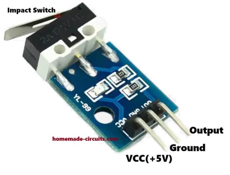
How the Module Looks Like?
Mostly the sensor module has:
- The collision switch (the small metal sensor) mounted on PCB.
- A pull-up or pull-down resistor already fitted.
- 3 pins coming out:
- Vcc (+ supply).
- GND (ground).
- Signal output (goes HIGH or LOW when hit detected).
- Some modules also have a small LED that blinks when impact is detected, but not all versions.
Working Principle
It is super simple:
When idle, the output stays normally LOW (or HIGH, depends on wiring).
When you tap or strike the module lightly, then contacts touch inside.
Instantly, the output pin changes state (LOW to HIGH or HIGH to LOW) for a short time.
After the impact is over, then it goes back to its original idle state.
It can be used to trigger alarms, counters, robots or any system which needs to react to a physical hit.
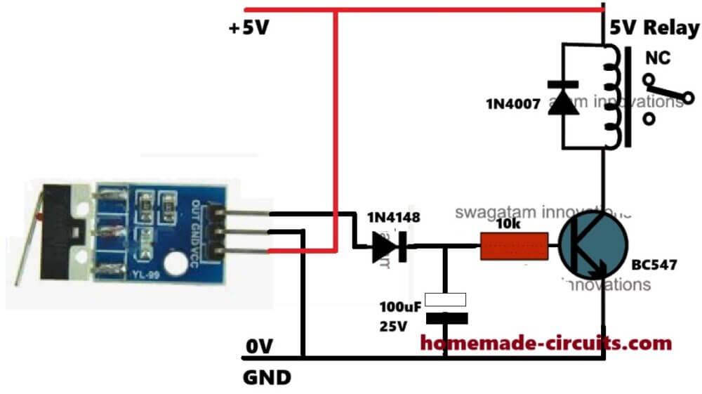
Analogue Relay Driver Circuit
The following diagram shows how to integrate the impact collision switch sensor with a relay driver circuit with delay OFF:
Typical Connection Diagram
Here’s how you can connect it to a microcontroller like Arduino:
(+) Vcc ----> +5V Arduino
(-) GND ----> GND Arduino
(Signal) OUT ----> Any digital pin (example D2)
And in Arduino code, you just check if the pin becomes HIGH when impact happens.
Arduino Code Example for Impact Collision Switch Sensor
// Define pin numbers
const int impactPin = 2;  // Impact sensor output connected to digital pin 2
const int ledPin = 13;    // Built-in LED for indication

void setup() {
  // Set pin modes
  pinMode(impactPin, INPUT);
  pinMode(ledPin, OUTPUT);

  // Start Serial Monitor
  Serial.begin(9600);
  Serial.println("Impact Sensor Ready...");
}

void loop() {
  // Read the sensor output
  int sensorState = digitalRead(impactPin);

  // Check if impact is detected
  if (sensorState == HIGH) {
    Serial.println("Impact Detected!");
    digitalWrite(ledPin, HIGH);  // Turn ON LED
    delay(200);                  // Keep LED ON for 200 ms
  } else {
    digitalWrite(ledPin, LOW);   // Turn OFF LED if no impact
  }
}
How this code works:
- impactPin is where you connect the signal output of the sensor (like pin D2).
- It keeps reading the sensor output inside the
loop(). - If it sees HIGH (impact detected), then it will:
- Print "Impact Detected!" in the Serial Monitor
- Switch ON the onboard LED at pin 13
- After a short delay (200ms), then it goes back to normal.
Wiring Summary Again:
| Arduino Pin | Module Pin |
|---|---|
| 5V | Vcc |
| GND | GND |
| D2 | Signal OUT |
Important Features
- Simple and Cheap: No complicated parts inside.
- Very Sensitive: Even small taps can trigger it.
- Fast Response: Almost instant switch ON when impact detected.
- Low Power: Works directly with 3.3V or 5V supplies.
A Small Hint:
- If your sensor is too sensitive and gives false hits, then you can add a small capacitor (like 0.1uF) across signal and GND to reduce noise.
- You can also add a software debounce if needed to get a better stability.
Arduino Code Example (Flip-Flop / Toggle Mode)
// Define pin numbers
const int impactPin = 2;  // Impact sensor output connected to digital pin 2
const int ledPin = 13;    // Built-in LED for output

// Define a variable to store toggle state
bool ledState = false;

void setup() {
  pinMode(impactPin, INPUT);
  pinMode(ledPin, OUTPUT);

  Serial.begin(9600);
  Serial.println("Impact Sensor Toggle Mode Ready...");
}

void loop() {
  // Check for impact
  if (digitalRead(impactPin) == HIGH) {
    // Change the ledState to opposite
    ledState = !ledState;

    // Set the LED accordingly
    digitalWrite(ledPin, ledState);

    // Print current state
    if (ledState) {
      Serial.println("Impact Detected: LED ON");
    } else {
      Serial.println("Impact Detected: LED OFF");
    }

    // Wait for impact to settle (debounce delay)
    delay(300);
  }
}
How this code works:
- ledState variable holds whether LED is currently ON or OFF.
- Each time a tap is detected, it inverts the ledState (
!ledStateflips it). - Then it writes the new state to the LED.
- It also prints a message to Serial Monitor showing LED ON or OFF after each tap.
- Small delay added (300ms) after a tap to avoid multiple triggers from a single hard tap.
Small Tip:
- If you want more stable behavior, then you can use longer debounce delay (like 500 ms).
- You can even add a buzzer instead of the LED if you want sound feedback, ok...
Summary Function:
| One Tap (Impact) | Result |
|---|---|
| 1st Tap | LED Turns ON |
| 2nd Tap | LED Turns OFF |
| 3rd Tap | LED Turns ON again |
| 4th Tap | LED Turns OFF again |
and so on... like a real flip-flop.
So guys, now you can use your Impact Sensor like a real physical ON/OFF switch for any project like controlling lights, buzzers, motors, just simply by tapping on the contacts...
Arduino Code Example (Relay Control Flip-Flop)
Let us now make the Relay Control Version of our Impact Collision Switch Sensor Module project so that you can control AC bulbs, fans, anything just by tapping on the switch.
// Define pin numbers
const int impactPin = 2;   // Impact sensor output connected to digital pin 2
const int relayPin = 8;    // Relay module control pin connected to Arduino pin 8

// Define a variable to store toggle state
bool relayState = false;

void setup() {
  pinMode(impactPin, INPUT);
  pinMode(relayPin, OUTPUT);

  Serial.begin(9600);
  Serial.println("Impact Sensor Relay Control Ready...");
}

void loop() {
  // Check for impact
  if (digitalRead(impactPin) == HIGH) {
    // Change the relayState to opposite
    relayState = !relayState;

    // Set the relay output accordingly
    digitalWrite(relayPin, relayState ? HIGH : LOW);

    // Print current state
    if (relayState) {
      Serial.println("Impact Detected: Relay ON (Load ON)");
    } else {
      Serial.println("Impact Detected: Relay OFF (Load OFF)");
    }

    // Debounce delay
    delay(300);
  }
}
How to Wire Everything:
| Arduino Pin | Connects to |
|---|---|
| 5V | Sensor Vcc and Relay Vcc |
| GND | Sensor GND and Relay GND |
| D2 | Sensor OUT pin |
| D8 | Relay Module IN pin |
Important Note for Relay Module:
- Relay modules normally activate when Arduino output is HIGH.
- But some relay modules are active LOW. (In that case, little code change might be needed.
- Be careful when connecting AC mains. Use proper insulation and relay modules that have opto-coupler protection.
How this Full Setup Will Work:
| Event | What Happens |
|---|---|
| 1st Tap | Relay turns ON - Bulb ON |
| 2nd Tap | Relay turns OFF - Bulb OFF |
| 3rd Tap | Relay turns ON - Bulb ON |
| 4th Tap | Relay turns OFF - Bulb OFF |
| And so on... |
Safety Tips for Relay and AC:
- Always use ready-made relay modules with isolation.
- Do not touch AC parts when you are testing.
- Use fuse if possible in AC line for increased safety.
Hints for Practical Projects:
- Touch/Impact controlled Table Lamp.
- Impact triggered Fan Control.
- Tap to switch ON/OFF Decorative Lights.
- Security System where you want shock impact can toggle ON a siren.
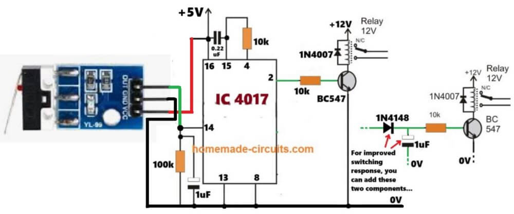
Analog Flip Flop bistable circuit Interfacing using IC 4017
If you want to interface the Impact collision switch circuit with a discretely built 4017 based flip flop circuit using IC 4017, then you can try the following concept:
Main Applications
So friends, you can use this sensor in many interesting ways:
- Anti-theft alarms (if someone moves your device, it can detect it)
- Robot collision detection
- Smart toys (react when shaken or tapped)
- Smart furniture (tap to switch ON lights)
- Industrial machines (vibration alarms)
Pros and Cons
| Pros | Cons |
|---|---|
| Very simple and low cost | Not accurate for very light vibration |
| Easy to connect | Can false trigger if environment too shaky |
| Good for DIY beginners | Cannot detect exact strength of impact |
Conclusion
Ok so in simple words, the Impact Collision Switch Sensor Module is like a sensitive tap sensor.
When you hit it, it closes a switch for a short moment and that can be used by a microcontroller or alarm system to know that "something has hit me."
If you want cheap and easy collision detection without using heavy complex accelerometers, then this module is the best buddy.
Just solder 3 wires, little bit coding and you are ready to go!
Need Help? Please Leave a Comment! We value your input—Kindly keep it relevant to the above topic!