In this post you will find the complete datasheet, pinout specifications of the IC LM358. This datasheet is written in simple language so that even the new hobbyists are able to grasp the technical details of the IC quickly.
The IC LM358B offers two high-voltage (36V) amplifiers in a single chip making them cost-effective for various projects. These op-amps boast several enhancement, for easier circuit design:
- Lower power consumption: The ic LM358 uses less power (around 300 µA per amplifier), ideal for battery-powered applications.
- Improved accuracy: it has a lower offset voltage (as low as 2 mV for some versions), minimizing errors in your circuit.
- Stable operation: it is internally compensated for stability, ensuring reliable performance without needing extra components.
- Rugged design: Built-in ESD protection and EMI/RFI filters make them suitable for harsh environments.
The LM358 op-amps come in various package sizes including compact options like SOT23-8, for flexibility in your circuit design.
Main Electrical Specifications
| Parameter | Value |
|---|---|
| Supply Voltage Range | 3V to 32V (single supply) / ±1.5V to ±16V (dual supply) |
| Input Offset Voltage | Typically 2 mV, Maximum 7 mV |
| Input Bias Current | Typically 20 nA, Maximum 250 nA |
| Input Offset Current | Typically 2 nA, Maximum 50 nA |
| Common-Mode Input Voltage Range | 0V to Vcc - 1.5V |
| Large Signal Voltage Gain | 100 dB (typical) |
| Output Voltage Swing | 0V to Vcc - 1.5V |
| Slew Rate | 0.3 V/µs (typical) |
| Gain Bandwidth Product | 1 MHz (typical) |
| Output Current | 20 mA (maximum) |
| Power Consumption | 0.7 mW per amplifier at ±5V |
| Operating Temperature Range | 0°C to +70°C (LM358N) / -40°C to +85°C (LM358A) |
Here's a detailed datasheet and pinout specifications of the IC LM358:
Pinout Details
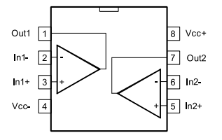
The LM358 is an 8-pin integrated circuit (IC) with two independent operational amplifiers inside. Here's a breakdown of the LM358 pinout:
Please note, the LM358 contains two independent op-amps, so each half (Pins 1-4 and Pins 5-8) functions as a separate amplifier circuit. You can find a visual representation of the pinout diagram in the LM358 datasheet, from various manufacturers like Texas Instruments or Onsemi.
| Pin | Function | Description |
|---|---|---|
| 1 | Output A | This pin outputs the amplified signal from the first operational amplifier (Op-Amp 1). |
| 2 | Inverting Input A | This pin is one of the two input terminals for Op-Amp 1. The voltage difference between this pin and the non-inverting input (Pin 3) determines the output on Pin 1. |
| 3 | Non-Inverting Input A | This pin is the other input terminal for Op-Amp 1. The voltage difference between this pin and the inverting input (Pin 2) determines the output on Pin 1. |
| 4 | VCC | This pin is the positive power supply for the LM358. The voltage on this pin typically ranges from 3V to 32V (depending on the version). |
| 5 | Inverting Input B | This pin is one of the two input terminals for the second operational amplifier (Op-Amp 2). The voltage difference between this pin and the non-inverting input (Pin 6) determines the output on Pin 7. |
| 6 | Non-Inverting Input B | This pin is the other input terminal for Op-Amp 2. The voltage difference between this pin and the inverting input (Pin 5) determines the output on Pin 7. |
| 7 | Output B | This pin outputs the amplified signal from the second operational amplifier (Op-Amp 2). |
| 8 | VEE/GND | This pin can be connected to ground (0V) for single-supply operation or to the negative power supply voltage for dual-supply operation. |
Detailed Electrical Specifications
Supply Voltage:
- Wide operating range: 3V to 36V (typical for B and BA versions). This makes the LM358 versatile for various applications with different power supply requirements.
Current Consumption:
- Low quiescent current: 300 µA per channel (typical for B and BA versions). This translates to low power consumption, making the LM358 suitable for battery-powered circuits.
Gain:
- Large DC voltage gain: 100 dB (typical). This high gain allows the LM358 to amplify weak signals significantly.
Bandwidth:
- Wide unity-gain bandwidth: 1.2 MHz (typical for B and BA versions). The unity-gain bandwidth defines the frequency range where the op-amp operates linearly. A high bandwidth allows the LM358 to handle a wide range of signal frequencies.
Application Circuits
Mobile phone RF Detector Circuit
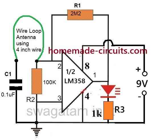
The LM358 op-amp may be used to build a mobile phone RF detector circuit which senses radio frequency (RF) signals sent out by operational mobile phones, a summary of a little description of how it works is given below.
How It Operates
Signal Detection: The antenna detects RF signals transmitted through the mobile phone. These signals produce a voltage shift in the associated capacitor.
Amplification: The LM358 op-amp boosts the detected signal. As soon as the RF signal exceeds a particular threshold then the op-amp's output becomes high.
Output Indication: This output triggers an LED indication or buzzer to indicate that a mobile phone is operational near to you. As long as there is an RF transmission, the LED flashes or continues to remain on.
Proximity Detector Circuit
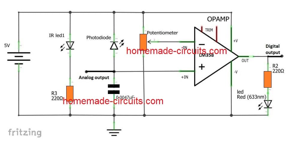
The LM358 op-amp may be advantageously employed in a proximity detector circuit which commonly includes an infrared (IR) LED and a photodiode or phototransistor. Heres a simple description of how this circuit works.
How it Works
Emission: Infrared rays is transmitted towards the monitored region by the IR LED.
Reflection: When an object enters range, then the produced IR light hits the object and bounces back to the photodiode.
Detection: The photodiode transforms the reflected infrared light into a tiny current causing a voltage drop across the associated resistor.
Signal Processing: This voltage is sent into the LM358's non-inverting input, whereas a reference voltage (adjusted via a potentiometer) is hooked up to the inverting input.
Output Response: In the event the voltage from the photodiode goes above the reference voltage then the LM358's output becomes high indicating that an item has been detected. If not, then the output logic will stay low.
Battery Charger with Auto Cut-off
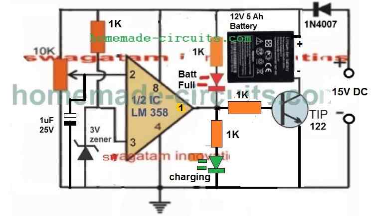
The LM358 op-amp may be programmed to provide a battery charger with automated shut-off, avoiding the requirement for a relay. This circuit is excellent for charging batteries such as lead acid and lithium-ion.
How It Works.
Charging: As soon as the battery voltage drops, the op-amp output turns high, triggering a transistor that enables current to pass from the power supply to the battery.
Cut-Off: As soon as the battery voltage hits a predefined threshold (for example 12.8V), then the op-amp output turns low, cutting off the transistor and terminating the charging operation.
Auto Reconnect: We can use an additional opamp from the IC LM358 for the auto restore or the auto reconnect feature. In the event the battery voltage drops below a lower threshold (e.g 11.5V), then another op-amp can tell the transistor to switch back on and resume charging.
Input Range
Common-mode input voltage range includes ground. This is a crucial feature for single-supply applications. It allows the LM358, to amplify signals with a reference voltage close to ground.
Differential input voltage range can handle voltages up to the supply voltage. This specifies the maximum voltage difference which could be applied between the two input terminals of the op-amp.
Input Offset Voltage Temperature Drift: The LM358 datasheet specifies, just how much the input offset voltage (a small voltage difference between the inputs that causes an output voltage even with zero input) changes with temperature. This drift can be important in precision applications in which temperature stability is crucial.
Slew Rate: This parameter specifies the the maximum rate of change of the LM358's output voltage. It's important for applications involving fast-changing signals, for example like pulse width modulation (PWM) or signal differentiation.
Short-Circuit Protection: The LM358 can withstand accidental short circuits on its output without a permanent damage. However there are limitations to this protection, and exceeding the current limits can still damage the device.
Noise Performance: The datasheet specify the noise level generated by the LM358 itself. This noise can add to the signal being amplified and needs to be considered in high-gain applications.
Applications:
The LM358's versatility makes it suitable for various applications, including:
- Signal amplification (voltage and current)
- Inverting and non-inverting amplifiers
- Differential amplifiers
- Comparators
- Active filters
- Simple signal conditioning circuits
Alternatives: While the LM358 is popular, there are other dual op-amps available with different features or improved specifications. Some considerations for choosing alternatives include:
- Rail-to-rail output swing (ability to swing the output voltage to both rails of the power supply)
- Higher bandwidth
- Lower noise
- Lower power consumption
- Higher input impedance
Other Specifications:
- Low input offset voltage: typically around 2-3 mV (depending on version). A low offset voltage minimizes errors introduced by the op-amp itself.
- Low input bias current: This parameter signifies the amount of current drawn by the input stage of the op-amp. A low bias current is desirable, to avoid affecting the signal being amplified.
- Internal frequency compensation: This ensures stable operation of the op-amp... without the need for external components for most applications.
- Large output voltage swing: The output voltage of the LM358 can reach close to the supply voltage on the positive side, maximizing its usable output range.
ESD (Electrostatic Discharge) protection (for B and BA versions): This feature protects the LM358 from damage caused by electrostatic discharge, which can occur during handling.
Integrated EMI/RFI filters (for B and BA versions): These filters help to suppress electromagnetic interference (EMI) and radio frequency interference (RFI), improving the signal integrity in noisy environments.
Package Options:
- The LM358 comes in various package options like TO-99, CDIP, SOIC, PDIP, etc. The choice of package depends on factors like size constraints and available PCB space.
References

Comments
can it be used to make an audio amplifier? if possible please make the circuit sir!!
Andre, you can use the following circuit and replace the opamp with LM358 opamp to make an amplifier:
https://www.homemade-circuits.com/power-amplifier-circuit-using-ic-741-and-mosfet/