Starting from a classical linear regulation, we will present the evolution towards a simple switching version. This will allow us to analyze the operation without going through the classical theoretical developments. In other words, a "practical" view of things. You can use the proposed design to significantly increase the backup time and efficiency of a battery-powered device. By: Chloé Chloé
IC 7805 Linear Mode
Linear power supply We assume that most of our readers have already used the 78xx series regulators, whose basic diagram is shown in Figure 1.
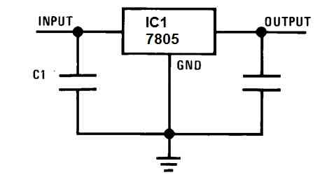
With a 7805, the output is of course fixed at a potential of 5 V, and the input must receive a minimum of 7.5 V to obtain proper operation. The two capacitors are decoupling capacitors that prevent possible oscillation of the regulator.
C1 is the "reservoir" capacitor that filters the DC voltage from a rectifier. Another "reservoir" capacitor is often provided at the output (C2), but of lesser capacity.
This type of power supply has been satisfactory for a long time, but it has a major flaw: as soon as the current supplied to the load exceeds a few tens of milliamperes, the regulator begins to heat up significantly.
If one wishes to deliver the maximum allowed current of 1 A for a TO220 package, one must resort to a sizable heatsink. This dissipated heat is a waste of energy that we seek to limit as much as possible, especially when powering a prototype with batteries or accumulators and when one wants to obtain significant autonomy.
Moving Towards a Switching Topology
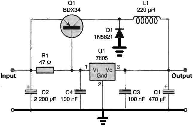
It is clear that a switching regulator is needed. To access it, you may be surprised to learn that only four components need to be added to the previous circuit diagram. You will find this evolution in figure 2.
At first glance, this diagram may seem a little perplexing, but you will find that the operation is simple. Two operating conditions need to be considered:
- a current in the load is less than thirty milliamperes
- a significantly higher current.
In the first case, the regulator alone performs the work, and the complementary components are inactive. Therefore, the operation is in linear mode (figure 3a), and the output provides a perfectly continuous 5V voltage. In the second case, the load is such that the current consumed is greater than 30 mA.
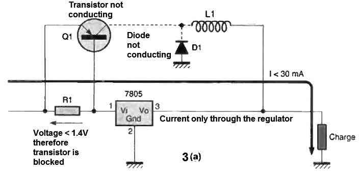
You should know that a Darlington transistor becomes conductive when the voltage between the base and emitter is around 1.4 V.
The 30 mA in the load also passes through resistor R1, so a voltage of 1.41 V (47 ohms x 30 mA = voltage drop across R1) appears across it. As a result, the transistor conducts and supplies current to the output through inductance L1. Energy is then transmitted to the output, powering the load. The output voltage will quickly exceed 5 V (figure 3b).
The 7805 regulator adapts to the situation and no longer supplies current to the load. Therefore, there is no more current in R1, no more voltage across R1, and the transistor is no longer conducting. This is the end of phase (b) of the waveform.
We remind you that an inductor (also called a "coil") opposes any rapid variation in the current passing through it. The transistor no longer conducts, but due to its nature, the inductor opposes the sudden interruption of the current.
It has stored electromagnetic energy that must be used. It is also called a "storage inductor" or "choke coil." This energy can continue to flow through a new path because diode D1, which had no role until now, is placed in such a way that it automatically becomes conductive (figure 3c).
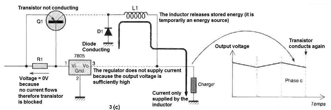
The inductor can thus continue to supply current to the load, but the energy it can release is low, and the output voltage will quickly decrease. After a few tens of microseconds, it will drop below 5 V. The regulator, which still monitors the output, will therefore "resume service" and supply the necessary current. And the cycle starts again, with the transistor becoming conductive again, powering the inductor, etc.
The variations in the output around 5 V are small, on the order of 20 mV. They can vary depending on the regulator manufacturer. The precise frequency of the cycle depends on the current in the load, the characteristics of the regulator, and the value of the inductance. It is around 30 kHz.
Performance
To demonstrate the interest of this technology, we measured voltages and currents at the input and output of this power supply loaded with a resistance of 2.35 Ω (Table I). The current in the load is therefore close to 2 A.
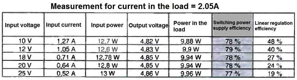
You can see that about 80% of the energy supplied at the input is returned to the load. We only lose "only" 20% of the energy. If we had used a conventional regulation, the efficiency would have been between 19% and 48%. This time, we would have lost between 50% and 80% of the energy, and the regulator would consume up to four times more power than the load!
Now you understand why switching regulators are used today in most electronic devices. They are essential when reducing the consumption of a device is desired.
Notice the specificity of this type of power supply: when the input voltage increases, the current supplied to the load decreases. It is surprising, but perfectly normal because the power supplied at the input remains roughly the same (P = voltage x current).
In a "linear" regulation, the current remains constant (the same as in the load), and the supplied power becomes increasingly important, which explains the difference in efficiency.
However, a switching regulator does not only have advantages. The switching generates high-frequency harmonics: it is preferable to provide a metal casing connected to the ground to avoid disturbing sensitive electronics. Therefore, it is a technology that is poorly suited, for example, for an audio preamplifier.
IC 7805 Switching Regulator Circuit
The final schematic can be found in Figure 4. We added a rectifier bridge so that you can directly use the voltage from a transformer secondary. The circuit is simple enough for all types of etching to be possible. In the case of direct etching, be careful about the width of the tracks, which should not be too thin.
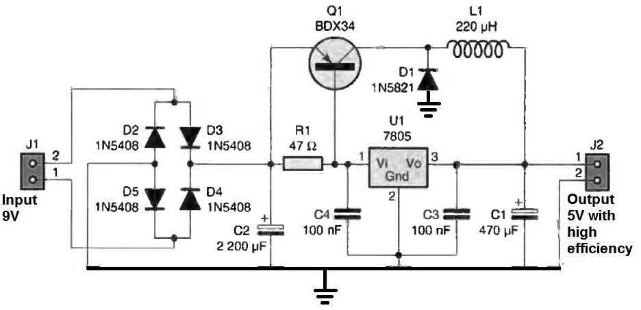
The inductance does not have a critical value. The one we used is a 220 uH self-given for a maximum current of 5 A, from Electronic Diffusion. You can use a value ranging from 150 uH to 800 uH, only the efficiency may be slightly different. It is imperative that the core and the enamel wire are dimensioned for a current of a few amperes.
The transistor must imperatively be a Darlington. The BDX34A that we chose is a high-current transistor. D1 is a Schottky diode, characterized by a very low voltage drop and excellent switching characteristics. The circuit will work if you use a simple rectifier diode, but the heating of the diode will be significant and the efficiency will be significantly degraded.
The 7805 can be a 78L05 plastic package TO-92, as on our prototype, or a 7805 package TO-220. The performance will remain the same in both cases.
The small heat sink for TO-220 that we used is suitable for a current consumed in the load of up to 2 A. Beyond that and for continuous operation, it is necessary to resize it. Note that with a well-adapted heat sink, this board can provide a current of 5 A.
How to Use
Connect your board to an AC voltage between 9 V and 24 V RMS and measure the output voltage in the absence of any load. You should get between 4.75 V and 5.25 V. If not, double-check the orientation of the regulator and the value of R1.
You can then connect a load to the output, such as a simple 47 Ω / 1 W resistor. The delivered current will be sufficient for the switching to be active. If you still measure the same output voltage as when the load was absent, everything is working correctly. Otherwise, check the orientation of the transistor and diode D1.
If you have an oscilloscope, you can observe the chopped voltage on the transistor collector. You can then visualize the influence of the current flowing through the load on the switching frequency.
Conclusion
To conclude, this simple switching regulator does not claim to match the performance of specialized circuits that can achieve efficiencies of over 90%.
The goal is primarily to show that switching can be implemented with commonly available materials. This simple circuit allows for easy analysis. The operating principle remains the same when using specialized circuits.
Now that you understand the principle, you can consider obtaining other voltages than 5 V by simply changing the regulator type: 7812 for 12 V, 7815 for 15 V, etc. You can even consider a variable regulator type LM317.


Comments
Hi Mr. Swagatam;
My desktop makes the keyboard defected For instant some keys like z, x and d letters were out or order on its own key board then I placed external usb key board
and at the beginning while only z and x keys were out of order but in time later some other keys also were added to the defective list on the external keyboard and now the keys like. “z, x, d, ü, i” and also some other sign keys were out of order I have a suspicion on that there may be a problem at the 5V usb line and as if the voltaga fluctuate some time So could you please advise taht I should change the capacitors around the 7805 or also
change the 7805 too?
Hi Suat,
Since I do not know much about the internal working of computer keyboards it is difficult for me to troubleshoot the fault.
However, regarding the 7805 IC, these have internal short circuit and over current protection, so mostly the Ic cannot get damaged unless the input voltage is exceeded beyond a specified limit. Similarly if the capacitor voltage ratings are above the input supply, then the capacitors also cannot get damaged. So the actual fault can be diagnosed only by practically checking these items or by replacing them with new ones.
Thanks Swagatam no problem
it was interesting so I wrote again that when I test the keyboard with the desktop
too then I see the same result that the keyboard is really defective
so that means there should be the something wrong with the usb system of the
laptop since the keyboards are being defected As a result the problem should be on either the 5V line or the data line. On the other hand each time and always same keys are being defected some period later. I will look for a talented PC
repair shop.Regards
No problem Suat, I understand the situation, I hope you will find a qualified technician who can solve this problem for you quickly…