This programmable timer can be used for switching a load ON and OFF with two sets of time delays, which are programmable from 2 seconds to 24 hours independently.
The delay timings are adjustable according to the users personal specs. The ON time delay and the OFF time delay are independently settable and this facility becomes the most important feature of a programmable timer circuit.
Using Versatile IC 4060
In this page I will elucidate a very simple yet reasonably useful timer circuit diagram whose ON time and OFF time settings are independently adjustable through ordinary pots.
The idea becomes so easily configurable due to the versatile IC 4060 which require minimal number of component for getting the unit running.
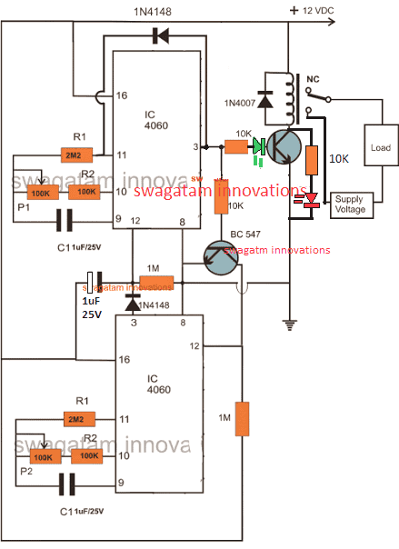
Looking at the CIRCUIT DIAGRAM below we can see that two inexpensive IC 4060 have been wired up as two independent timer modes.
However though the timing settings are independent for the two sections, these are coupled with other such that their initialization become very much interconnected.
Basically both the configurations are similar and have been rigged in the standard counting modes of the IC 4060 devices.
You may also want to make this Arduino based programmable timer circuit
How the Circuit Functions
The output of the upper IC is coupled to the reset input of the lower IC via a transistor in such a way that once the upper IC's output goes high, it triggers the lower timer into operation.
The lower IC then starts counting and when its output goes high, it halts the upper ICs counting and resets it to its original state and the process is initiated back from the start.
It simply means that as long as the upper ICs timing does not lapse the lower IC remains idle, however once the upper ICs timing lapses and its output becomes high, it switches the output load as well as the lower ICs operation.
The pot associated with the upper IC can be used for determining after how long the load will be switched ON, while the pot associated with the lower IC is used for determining how long the load remains in the switched ON position or simply after what time it should be switched OFF.
Update:
The LED positions have been changed in the following updated designs, because the earlier LED positions were conflicting with the relay operations, and therefore the positions have been relocated for ensuring foolproof operations.
Circuit Diagram of a Versatile Programmable Timer
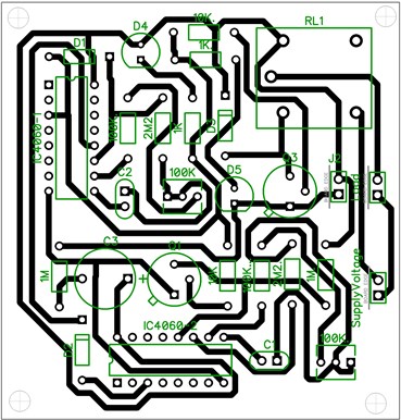
PCB Layout
Video showing the proposed 2-stage programmable timer circuit with LEDs
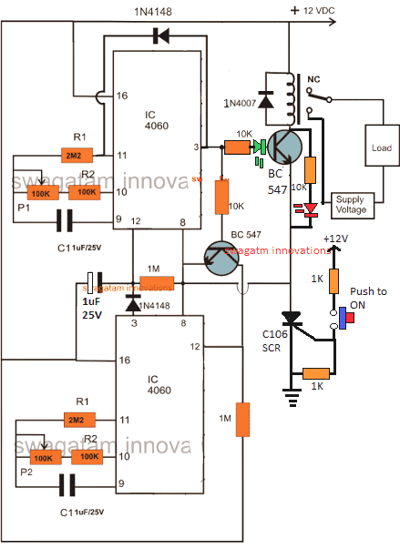
Using a Start Push-Button
The above design could be upgraded with a push-button to facilitate a push button start. This further ensures that the timer shuts off completely in case a power failure occurs while the circuit is operational, which in turn ensures that crucial loads like heater, or geyser are completely turned OFF during such situations.
Calculating RC Timing Components
It can be done through a formula, but the manual way is much simpler and accurate. It can be done as I have explained below:
- Connect any arbitrarily selected resistor above 100K in place of P1/R2 in the upper circuit.
- Switch ON and carefully note down after how much time pin#3 of upper IC 4060 becomes HIGH. This will be your "sample delay".
- Once this is noted, the other desired time delays could be calculated using the following simple cross multiplication:
Sample Delay / Desired Delay = Selected Resistor / Unknown Resistor
For example if you find the pin3 becoming high after 300 seconds, this becomes your sample delay value.
Now, we have the sample delay and the resistor value responsible for this delay.
Therefore if we assume the desired delay to be 1 hour or 3600 seconds, we can calculate it by substituting the values in the previous equation:
Sample Delay / Desired Delay = Selected Resistor / Unknown Resistor
300 / 3600 = 100 / x (unknown resistor)
300x = 360000
x = 1200 k or 1.2 Meg
This shows that 1.2 Meg in place of the P1/R2 will produce the required delay of 1 hour at pin3 of a IC 4060
Please note that the above calculation is only an example and the values do not indicate the actual results.
Customizing the Above Concept
This circuit of a flexible programmable timer circuit I have explained in this article was designed by me in response to a request by Mr.Amit. Let's know more about the request and the circuit details.
Technical Specifications
I need a circuit for my aquarium where it should do the following:
It should switch off the lights at 10:00 pm and start at 7:00 am daily + switch off the light at 12:00 pm daily and switch up at 6:00 pm back.
This will help to make my fishes live longer. 🙂
Thanks in advance.
Amit desai
The Design
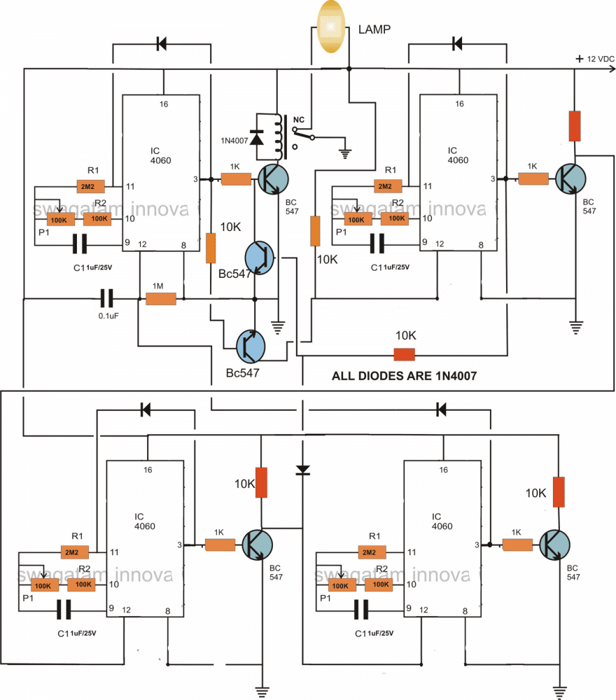
So here's the circuit that I came up with. As the name suggest, the timer is pretty flexible and may be adjusted to produce any desired time periods, according to the above requested format.
The circuit consists of four identical stages, made up of the IC 4060 timer configuration. Te timer sequence begins from the IC at the top left corner.
When power is switched ON this IC starts counting. Depending upon the setting of its pot, the IC triggers after a certain period og time interval.
This switches ON the relay and the driver transistor BC547 which consequently switches OFF the connected lamp. The stage gets latched with the help of the diode connected across its pin 3 and pin 11.
The above triggering also switches another BC547 transistor which connects the reset pin of the next IC 4060 to ground which initiates this stage also.
After a predetermined time, this IC also triggers its output at pin3 and gets latched by the corresponding diode, however this actionsends a feedback signal to the relay driver transistor, instantly switching it off and restoring power back to the lamp so that it lights up again.
Just as the above actions, the sequence further proceeds and switches ON the third IC 4060 in the line which counts the set time interval and pulls the relay back to OFF position via the diode connected to the collector of its bc547 transistor, such that the lamp again gets switched OFF.
As soon as the above triggering happens the last section at the bottom right corner switches into action and counts as per the setting of the respective pot, until the ICs output becomes high, this high reset the the first IC and switches ON the lamp once again so that the process may be restart the cycle all over again.
The pots may be increased to 3m3 for generating higher time interval periods, so is true with the respective capacitors.
Circuit Diagram
How to Adjust and Set Up
The timer may be adjusted as per the sent request, in the following manner:
If we consider the first timing sequence to begin at 7am and end at 12pm, means the upper left timer's P1 needs to be adjusted such that it activates the relay and switches off the relay after exactly 5 hours.
For keeping the lamp switched OFF in the above position and switch it ON back at 6 pm we now adjust P1 of the upper right timer section such that its output triggers after another 5 hours. This switches ON the lamp again.
The above situation needs to be kept intact until night 10pm, which is about 4 hours of period, therefore we adjust the lower right timer's P1 to get it triggered after 4 hours of time interval.
Finally, for initiating the above procedure back again the next morning at 7am, P1 of the last timer at the lower right is adjusted such that it resets the first timer after 9 hours..... and the cycle repeats.
For making the circuit work according to the above specified timing pattern, after adjusting the respective hours, the unit should be powered or switched ON exactly at 7 clock in the morning....rest will automatically follow.
Cascaded Programmable Timer Circuit with Multiple Outputs
If you are looking for a programmable timer circuit having multiple outputs for controlling multiple loads and with individual time settings, then the following circuit will do the job for you.
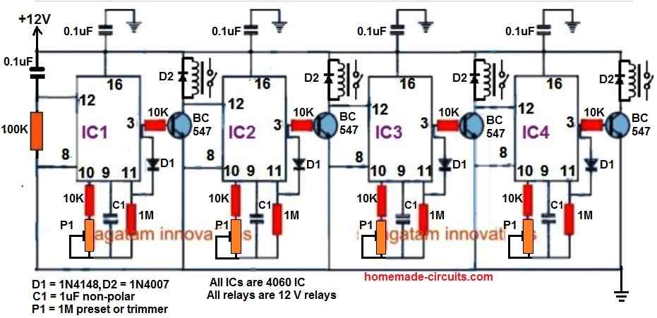
Here, a 4-step programmable timer circuit is shown, but you can add more number of 4060 stages to increase the number of cascaded outputs, as desired.
The time delay output of each 4060 timer stage can be individually adjusted and set using the relevant P1 preset.


Questions & Answers
I really hope someone can help me……
At the office I need one answerphone message during office hours and a different message out of hours. At the moment these are switched manually however on the odd occasions when I have to go elsewhere before going into the office, the out of hours message stays on until I can physically switch it over.
I thought of creating a standard programable timer that connects between the wall telephone socket and the two answering machines that can switch one machine off whilst switching the other on and vice versa.
I originally thought of just using electric timers as can be bought in a shop however if the power is disconnected to an answering machine then it is reset and may not work properly when switched back on without physical intervention. So my thought is that both machines remain powered up but the switching actually happens on the telephone line.
I think it should be straight forward however I have not been able to find anything that can achieve this. Any help or circuit design ideas would be very much appreciated.
Thank you.
Hi sir,
I need a circuit for a motor that pumps water for appr. 15sec daily. I would like to program the timing(15sec) in MC. Is it possible.. can you please help
I'll try to do it, let's see….
HELLO SIR..
SIR THIS HELP IS ABOUT COMPUTER LOGIC DESIGNING SUBJECT.
SIR MY TITLE IS TO MAKE DIGITAL CLOCK USING COUNTER.
BRIEF DISCRIPTION : I CAN USE DIFFERENT GATES(AND,OR,NOR E.T.C) AND COUNTER .PIC OR OTHER IC PACKAGE IS OT ALLOWED .
PROJECT IS ABOUT 25 MARKS. THIS MEANS THIS SHOULD NOT BE SIMPLER ACCORDING TO MADAM.I HOPE SIR YOU UNDERSTAND MY NEED
I HOPE YOU IS THE PERSON WHO CAN HELP ME..
THANKSS …..
digital clock may refer to a device for checking time, or a frequency generator circuit….which one u are referring to?
sir it is used for the time.
sorry i do not have a time clock circuit using gates only.
SIR THIS INCLUDE COUNTER AND GATES. THE LIMITATION IS ABOUT IC PACKAGE. CASCADING OF IC'S IS ALLOWED
I don't have any such circuit with me, I will try to find it, if i get will inform you.
hi dear…
can i use the above circuit to keep relay ON for 5 sec and keep relay OFF for next 30 minutes..and after 30 minute the ralay automatically ON again for 5 sec and thin OFF for 30 Minutes and this process repeat again again
yes you can, the above circuit is exactly for this kind of applications….
THis is not a blinker, rather a timer circuit.
Anyway if you are using it as a timer, do the the following:
You can remove the transistor/relay assembly and connect one of the LEDs LED across the existing 1K resistor and pin#7 of the IC. Anode will connect with 1K and cathode to pin7.
For the second LED, you have to repeat the procedure, connect another resistor at pin3 of the IC, connect the LED across the free end of this resistor and pin7 of the IC….polarity same as explinaed for the first LED.
The LED cathodes are connected to pin7 so that they blink when the time elapses
The above circuit is not for controlling blinking or flashing rate of an LED.
It's a programmable timer circuit.
I'm hoping you can answer a question asked earlier. "Can I connect the load directly to the circuit instead of using a relay?" Or if not, can i use the same 12v power for the load/relay side and the timing circuit side?
I am wanting to use this circuit to run an air circulation fan (12v computer case fan) system in a cooling unit. But a 555 oscillation timer runs too much. I only need approximately 1 min on / 30 min off run time for the fan.
Thanks, Chase
A 12V fan can be directly connected across the transistor, but it will need to be upgraded to a higher rated (TIP122) transistor instead of the shown BC547.
Dear Guru …
I need circuit for time limiter to use for public speaking.
Say if a teacher has one hour to speak in the class then the timer will show a green light starting from 60 minute then counting down to 0, but before finish the yellow light will turn on to remain a teacher that the time almost finish, it can be 3 minutes before to 0, finally when the time is over the red light will be on, it means that time for the teacher is finish.
Thanks & Regards,
ilman.gumilar@gmail.com
Dear Ilman,
I'll try to design the circuit and post it soon.
I have published it here:
https://www.homemade-circuits.com/2013/11/week-day-programmable-timer-circuit.html
Hi Swagatam,
Is it possible to add pwm to control 12V, 3A motor in this circuit? Thanks
Hi Charlie,
Yes it can be done, in your previous comment I have suggested you the required PWM controller circuit. You can simply power that circuit via the relay contacts of the above circuit, so both get integrated for the intended results.
Hi Swagatam,
I am trying to build a circuit to help me with giving speeches. I have a bunch of parts already and I would like to use them if possible. I want it to have an On/Off switch to power the circuit and a Start/Stop button as well as a Reset button. I would like for it to light a Green LED after 5 mins, then turn off the green LED and light an Amber LED at 6 mins, and then turn off the Amber LED and light a Red LED as well as sound a buzzer at 7 mins. I would also like to have a seven-segment display show the elapsed time. Let me know haw feasible this would be. Thanks.
Hi Sean,
I'll try to design it and post it soon for you.
Hey mate,
I am trying to understand the circuit with regards to the relays connection into the circuit. I realize this is perhaps 101 stuff however it is a hurdle for me at this stage in getting this circuit to function for me. Does the diode connect directly across the coil pins? How are the NC and NO pins connected? Is the common pin connected? Thanks your help is appreciated.
Hi Jason, it may be connected directly across the relay or anywhere in the PCB, it doesn't matter as long as it joins with the relay coil in the shown manner, that is cathode to the positive of relay coil and anode to collector side of the relay coil
NC or NO should be connected with the load via the supply voltage as per the requirements such that when it operates it makes or breaks the supply to the load alternately.
Thanks Swagatam,
I'm negative at the upper ic pin #15, you mention in your upper post that pin#15 should give indication of functioning circuit, can you expand please on this circuit diagnostic?
Thnaks again.
Also please what frequency would you expect the cycle if both pots were at their lowest resistance? (given correct components were used as per your diagram)
Yes pin#15 could be too slow with its blinking rate especially when the ICs are set with timing over 5 minutes, so won't serve as an effective indicator, I have updated the diagram with LED indicators for the respective indications.
The frequency formula is
F = 1/2.3RC….where R is ohms and C is in Farads
Thanks. However I'm still having problems with it. Would a correctly wired circuit illuminate the red LED whilst waiting for first timer period to trigger the second which will result in the red LED turning off and the green LED illuminating (as well as obviously closing the load circuit via the relay)?? I would just like to confirm this is the intentional use of the additional LED's. Thanks again for your help.
Yes, the moment the circuit is switched ON the red LED will light up, it will stay illuminated as long as the upper IC counts and will shut off once the upper time interval lapses.
This will prompt the lower IC to begin counting with green LED now being illuminated.
Your the man! Works a treat, thanks for all your help.
You are most welcome!
hi sir wats the ON and OFF time of the above circuit
It will need to be checked through practical testing
k thnks for the reply
hi sir i would like to build a circuit which should be on for 3 to 4 hours and gets off
you can try the following design:
https://www.homemade-circuits.com/2013/07/simple-triac-timer-circuit.html
hi
i m regular reader of your blog. I want the circuit as per following condition.
1) When power supply is on then relay on after 3 min.
2) After 3 min relay stay on for 2 hour then off even after power get failed at power on switch and continues run by 12 volt by load connection for 2hour.
can you guide me for this project.
you can try the above shown circuit.
adjust the lower section for 2 hour and the upper section for 3 min.
for battery backup connect a parallel battery supply through a 1N4007 diode. the mains power supply voltage to the circuit should be slightly higher than the battery voltage
Hi sir,
i assemble this circuit but not work properly. It shows that, relay start when power is applied but not Off as i adjusted the pot. I used polyster 1uf/250v capactitor NP. I dont know where is problem please guide me how can i take tests on circuit for example any voltage point.
Hi Ashok
I have designed and tested this circuit myself and it worked flawlessly.
The relay should not activate when switched ON, rather when the upper IC time has lapsed.
Something's severely could be wrong with your circuit connections.
Put an LED with 1k resistor at pin7 and ground of the ICs, when the particular IC is activated this LED will start flashing indicating proper IC functioning.
sir i check this i put 1 led with resistor at IC1 & IC 2 pin 7 both LED flashing at same intensity 3 flash per minute when power is supply & relay activate instantly. can you tell me where is my problem.? one question is that both 1uf/25v capacitor is Non polar ( polyster) & 0.1uf cap is ceramic? I used these parts.
Ashok, replace the capacitor in the upper section with 0.22uF and the lower with 0.1uF and now check….this modification will give quick switching and help to verify the functioning.
Connect another LED with the base of the relay driver transistor….check its response….relay should NOT activate on power switch ON
Sir the circuit is very nice. I made it successfully. I would like to suggest to those who are trying to make it they should make it in such a way where each ic should work individually and should not be interconnected. When both ic start working individually then they should be interconnected. I myself applied the same method and succeeded. Am I right sir?
Thanks Mujahid, you are right!
Sir kindly help me the ic4017 gives its sequential output when I am using oscillator circuit (that is 555 ic) I mean it is all ok with an oscillator circuit but when I manually give a positive pulse at pin 14 of 4017 it does not respond well please I need it
Mujahid, did you connect the pin14 to ground through a resistor? you must do this in order to make it respond to manual switching.
connect a 100k resistor from pin14 to ground and then trigger it with a positive pulse manually, it will surely respond.
Thank you sir I.ll try it.Sir i need a circuit similar to the one with ic4017 but the problem with ic4017 is that whenever pulse is given one output appears and the previous output disappears. The one I need should be opposite of it. I mean when i give 1st pulse there should be one output but when i give second pulse there should be two outputs and when i give 3rd pulse there should be three outputs and so on. No output should disappear.the pulse pin should be single like ic4017 Thank you
Mujahid, the IC 4017 will not produce latched outputs, its sequence will shut the previous output as it proceeds in the order.
For your application you would need the IC 74LS164, this will produce latched outputs as its output sequences.
thank you sir i need the above mentioned ic this is the exact device i was looking for.today i read about it but i would like you to explain it in your own way so i could understand it well. thanks a lot once again.
Mujahid, pls refer to the following post:
http://www.brighthubengineering.com/diy-electronics-devices/95093-moving-led-signs-using-ic-74ls164-pin-outs-explained/