The following article presents a very simple low current 220 V mains operated transformerless power supply circuit using an inexpensive MJE13005 transistor and few other passive electronic components.
As can be witnessed in the given circuit diagram, the design is extremely straightforward.
How it Works
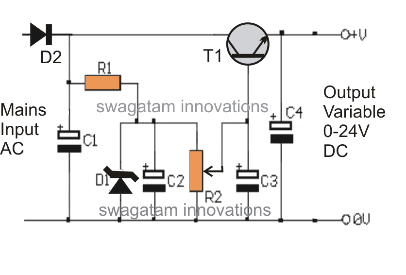
Transistor T1, which is a high voltage NPN transistor MJE13005 forms the main active component in the circuit.
Rest of the components are positioned just for supporting the conduction of T1 and for the required stabilization.
The circuit can be understood with the following points:
Mains input is fed across D2 and the negative line of the circuit.
D2 rectifies the mains AC, while C1 filters to some reasonable levels.
R1 drops the current to tolerable limits in order to provide the required base bias for T1.
C2 provides further filtration to the voltage generated after R1.
D1 clamps the base voltage at the base of T1 to 24V, such that the maximum output voltage can never exceed this limit.
A mirror voltage which is always equal to the zener value is generated at the output, however the presence of R2 enables the response to become variable.
The adjustments made through R2 effectively varies the zener voltage right from zero to the maximum value, that is up to 24V.
Thus the obtained output becomes variable from zero to 24V.
However since the voltage is acquired across the emitter/ ground of the transistor, the current gets restricted to very modest levels, at 25mA to be precise.
The zener voltage though may be increased to any desired limits.
WARNING: THE WHOLE CIRCUIT IS NOT ISOLATED FROM MAINS AC, THEREFORE IS EXTREMELY DANGEROUS TO TOUCH WHILE IT'S UNCOVERED, AND POWERED CONDITION. MAKE SURE YOU HAVE MAINTAINED ALL THE NECESSARY PRECAUTIONS WHILE HANDLING THIS CIRCUIT.
Parts List
R1 = 100k
R2 = 10K POT
C1 = 4.7uF/300V
C2 = 10uF/100v
C3,C4 = 100uF/30V
D1 = 24V, 1WATT, ZENER DIODE
D2 = 1N4007
T1 = MJE13005



Questions & Answers
can you please upload high power led driver circuit for 400w led.
you can use the following circuit:
https://www.homemade-circuits.com/2011/12/make-hundred-watt-led-floodlight.html
just replace the components by calculating them with the given formula.
You will need an external smps to drive the above circuit
Dear Aruna,
According to me there's no possibility of a surge in this circuit.
sorry 1 amp won't be possible.
hi
can you help me 5v-12v transformer-less power supply circuit
hi, what's your current requirement? please specify the current requirement.
about 500-1A cause i will use it to drive a TDA 2822M and charge two smartphones
For charging batteries you will have to employ an smps circuit, other forms won't be safe as these may not be isolated from mains AC and also not capable of producing higher current outputs.
What if i inverse the polarity of capacitors in this ckt ? They will explode right sir??
sir,
Do you have any circuit which provide 12v 100ma current…..
Avik, you can use the above circuit and add an overboard transistor across the existing mje13005 for boosting current to the required levels.
I'll try to update it soon here.
T1 is the main component which does the required voltage dropping.
Dear Sir,
The above circuit use in 23v/300ma Led light(7watts)
Thanks & Regards
S.Bharanidaran
Dear Bharani,
No, it's not suitable for high current applications.
Dear Sir,
Do you have any circuits high current application above my spec
Thanks & Regards
S.Bharanidaran
Dear Bharani,
According to me an SMPS would be the correct option choice for driving a high watt LED.
you can easily procure a readymade 24/1amp smps unit ad power your LED through
it….smps amp is not crucial as long as the voltage does not exceed above the led specs.
hi sir im a electronic hobbiest
can i use this circuit to power 100 led lights
Hi Vikram, use the following circuit, the above will not work:
https://www.homemade-circuits.com/2012/03/how-to-make-simplest-1-watt-led-driver.html
put all the LEDs in series and join it with the output of this circuit
Bro can I use this pcb with smd led? If yes then how much number of minimum qnd maximum led I cn use..,
Bro I won't recommended this circuit for SMD because SMDs are costly and we require foolproof design, so better go for a 12V SMPS adapter available readymade.
please translate in english
try a 400V capacitor for C1, or simply don't use anything, eliminate C1 and first try the circuit without it.
Which diode is wrong???
Is it the 24V zener or the general purpose 1N4007 ???
It's D1, I'll correct it in the article soon
Hello,
One question regarding your schematic : would it work with only the phase 220VAC line and no neutral.
I'm working on a power supply for a small radio module to controle light switch. behind the light switch I don't have the neutral line.
hello, you can use an "earthing" line as the neutral, for example it could be your bathroom water tap line…
Hello,
I'm sure you know this is very late asking a question regarding your design. Hopefully you will read this.
I see your parts list, but can you give values for the wattage for…. R1. Will this need adjustment in case of modifying the output, I've, if output is required at 12v, will RI wattage be different?
Many thanks
Rich
Hello, R1 is 1/4 watt rated..it's not recommended to adjust its value because lowering it can damage the transistor.
Hello sir,
I read all comments , and in several post, some ask you if it is possible to increase output current .
Your answer was NO ! , just because of non isolated circuit design. (Very dangerous)
Now, my search is about 5V – 250mA output, but also i don't need to be isolated. ( full non touch possible , sorry i don't know how translate)
I look lnk306, viper22a , etc , but not really cheap, and hard to get full work well.
So can you help me , or drive me to a way to get what i wish.
Thanks
Best regards.
Hello Stévanovitch
you can try the following design
https://www.homemade-circuits.com/2016/07/scr-shunt-for-protecting-capacitive-led.html
Sir i need 24 volt dc 4 amp. transformerless power supply circuit. my email is narmeenfarooq@gmail.com Sir PLZ quickly.
Farooq, you will need to make an SMPS circuit, capacitive version may not be recommended for such high current applications.
Sir, i knew i'll get electric shock if i touch this circuit. Would you like to suggest me how to make this circuit with transformer? Thanks
Riyan, you can try the following circuit
https://www.homemade-circuits.com/2012/05/cheapest-smps-circuit-using-mje13005.html
sir, I have AC 220/24 50Hz DC 12v ×2 500mA transformer. Pls is there anyway to make that 500mA to be 5Amp
Kabiru, getting 5amp from 500mA source is just not possible…
Hi Swag
I have a question on the circuit diagram, if we measure between collector and ground we should get rectified mains, not so? The zener diode only affects the base of T1. If that is correct wouldn’t we expect mains voltage at the output once the base is forward biased?
Hi Sidingilizwe, the collector ground voltage will be apulsating DC at around 300V if the filter capacitor is good.
The zener diode forces the transistor to allow only around 24V DC at its emitter side which is turned into pure DC due to the presence of C4.
please prince of electronics Swag, I request you to design me a transformerless power supply 12v dc , 5amps
Kaluya, that may be difficult, and is not recommended
How to Increase the Amps from 5v transformer less power supply
It is not recommended!
sir can this circuit be using to set your twin/split charger if not what are the modification. i’m waiting for ur response thanks
Sorry this circuit cannot be used for charging batteries.
Good day sir ,I want to construct 1000watts inverter transformer the out put is the primary 220v and the input is 12v which is the secondary side. I want u to check if my calculations are correct
1000/12= 84amps
Secondary current 84
Secondary volt =12-0-12 equal to 24volt
Primary volt= 220v output
Output frequency=50hz
Finding the core area- 1.152*√24* 84=387
Calculating turns per volt= 1/(4.44*〖10〗^(-4)**387*1.3*50)=8.92
8.92 is my turns per volts
Number of turns for primary– 8.92*220= 1962.4
Number of turns for secondary – 8.92*24=214.08
Pls sir I will appreciate if you clear me on this.
Thanks GOD bless you
Youngking,
If you have put the formulas correctly then it should be correct, I don’t remember the formulas so it would be difficult for me to confirm the results.
good day sir, sir what i mean is concerning your twin/split charger that has change over which require variable power supply circuit to set the low battery cut off and fully charge cut off. now my question is as follows
1.can i use this transformerless variable power supply circuit to set this charger.
2.what component can i use to monitor this circuit when varing from 0-24v.
pls i’m waiting for your response
thanks
Youngking, do you mean to say you only want to power the IC circuit with the transformerless power supply and charge the battery from an external source through the relays?? I am not sure what you are trying to suggest? please clarify elaborately
sir, what i’m intended doing is to use this circuit to set low battery cut and full charger cut off for one of your charger I’m yet to build . I hope is clear now, but you have not responded concerning the video I sent to your mail. God bless u for your response so far
Youngking, Please do not use the above circuit, instead try the last circuit from this article:
https://www.homemade-circuits.com/1-watt-led-emergency-lamp-circuit-using/
ignore the 8550 transistor, the LED, and the 1N4007 diode, and use the output which is available across the 1K resistor.
Do not use 2uF at the input instead use a 0.33uF/400V
Remember all these circuits are extremely dangerous since these are not isolated from mains input, proceed at your own risk.
Regarding designing a transformer I am sorry, I cannot suggest much, because I have no experience with practical transformer designing, whatever I have published here are all referred from other sites or magazines.
thank you, i will do as you said
please explain what you mean by isolated from main input ,i know i’m asking too much sir.
it means AC 220V will be floating across the whole circuit and may produce a lethal shock if touched in switched ON condition
Dear, sir I want 24-0-24 dual power supply 10amps circuit diagram please send me my email address.thankyou sir
Kumar, you can build the following type of configuration:
use 24-0-24/10 amp transformer
Not related to the article. 🙂 Just want to say how wonderful it is to see someone that loves what they do and is willing to share their knowledge. Cheers!
Thank you very much, Glad you liked my website! Cheers!
Dear Sir,
i tried this ckt. but during first test the mje13005 had burst. the pcb track burst with loud sound.
can u please analyse? guide me. suggest the correction.
Shrishail Utagi
Hello shrishail, which load did you use in the circuit?
Dear Sir,
I use no load.
Thank you
Without load the transistor should not burn, that is strange. You can try a similar circuit which is shown here:
https://www.homemade-circuits.com/0-300v-variable-voltage-current/
Dear Sir,
Thank you for your kind attention.
I’ll definitely try this circuit.
Sure, no problem!
Hello Swagatam,
There are two reasons why MJE exploded (actually three)
First, the reader may have misconnected the MJE’s leg pins.
Second, the 100uF you use at the output of the circuit is a very large capacity value. When this capacitor is empty, it will act like a short circuit for the first 1-2 seconds when you apply DC to it. This is enough for the MJE and its main power line to explode. Therefore, you should change the 100uF value to a maximum of 10uF.
The third reason I mentioned in parentheses is that this circuit will never be safe and useful. You can use this circuit in nowhere! Because the circuit should not be connected directly to the main power line in this way. Regardless, I do not recommend that you risk their life and health by showing this circuit to your readers. I also make and use transformerless power supply. But I am absolutely aware of what I am doing, and I review the dangers that may be and, if necessary, do not share it with my readers.
Good work…
Thank you Shampuan, I appreciate your effort you’ve put in analyzing the fault, however except the first point, the remaining points may not be correct, I’ll explain you why.
As you can see there’s also a base capacitor C3 which ensures that the BJT conducts and charges the C4 slowly, negating any kind of surge current across the Collector/emitter pins.
Even if C3 is not included, the MJE13005 should be strong enough to handle the charging of C4, since its collector/emitter is rated to handle 4 amps at 400V continuously, while the charging of the 100uF would be in a few milliseconds, at 310V….C4 would be fully charged even before the current could reach 1 amp.
Now as far as the dangers of handling a transformerless power supply is concerned, I have already provided a warning message at the bottom of the post, and I am confident that my readers are wise enough to understand the dangers of electricity and will take the necessary precautions and care to evade any kind of mishap.
Even petrol and kerosene are dangerous, so should we put a ban on these fuels?
😀
No. Of course, we cannot ban gasoline and kerosene.
First of all thanks for the explanation.
The only thing I see as a drawback with the circuit is that it connects directly to the outlet voltage. In other circuits where we apply the capacitive reactance rule, we reduce the danger at least a little. I’ve also seen other transformerless circuits on your site. Pretty good job.
Judging from your explanation, it seems that the real fault cause of the circuit is not the capacitor. So now that we’ve eliminated this option, we can assume that the wrong connection or MJE could be fake. To be honest, I can’t think of anything else …
Surely I can understand your concern, and thank you for appreciating my circuits.
But I think the capcitive power supplies are also as life threatening as the above one, because the current even from the capacitor can be lethal enough to kill any human being if the connection is not removed within 5 seconds. Moreover, while plugging in the capacitive power supply the user has no idea at all whether the capacitor end is inserted to the LIVE or the other free end is inserted to the LIVE pin…if the free end goes to the LIVE then it becomes even more dangerous.
Nevertheless, thank you for your valuable feedback, hope the visitors will find the discussion helpful.
Hi there,
I am glad to see the circuit schematic presented here.
Now I need a cheap experimental circuit to generate 5.5 to 12 volts 50 amperes variable DC power supply without transformer and from line current of 220volts 5ohz. Any help there?
Thanks and best regards.
Hi, Thanks for your feedback.
50 amp is too high for any transformerless power supply and is not feasible.
You will need an SMPS design for achieving the requirements.
Thanks for the quick reply.
Now I got a new Idea. And it is variable transformer build using TV LOT ferrite cores as i have spare with me.
So now can you give me solution to build it with 220v 50 Hz input AC to out put with 5.5v 50amps , 12 volts, 24volts, 75volts, 100 volts, output, [ other than 5.5 and 12 volts all others could be less Amps output.] Please describe step by step construction of this Variable Transformer. Thanks for your very good and highly esteemed website and the help you offer to inventors like me. All the best and thanks again.
Thank you Vyas,
If you use a ferrite inductor then it will require a lot of calculations. Moreover, 50 amps would mean a hugely thick wire using Litz wire, which can be difficult for you to procure.
Dear Swagatam Sir,
Pl. go through following article on net and let me know your opinion as to whether it is feasible to use in my project.
rjtechunlimited.com/2024/09/7000-watt-regulator-perfect-and.html
Thanks and best regards.
Hi Vyas,
that circuit is nothing but a light dimmer circuit, which will produce AC voltage output, but if you convert it to DC, the voltage will increase to very high level, because the peak voltage will be high.
HI there,
So what cold be solutions for my problem. If nothingelse give me a circuit schematic for transformerless power supply for 5.5volts and maximum amps from 220vots AC supply.
ATB
I can provide you a 5 Amp max current circuit, which is shown below:
https://www.homemade-circuits.com/12v-5-amp-transformerless-battery/
You can adjust the output voltage to 5.5V by replacing the shown 13.5 zener diode with a 5.5V zener diode.
Thanks for the reply. Now let me know how to change 12volts 10amps to 5.5volts21amps. please reply instantly.
ATB
You can use the last circuit diagram from the following article, but the part values will need to be calculated as explained in the article:
https://www.homemade-circuits.com/calculating-inductor-value-in-smps/
Hi there,
I don’t know where you are put up. if I want o see you personally.
I have a problem with mu Digital Multi meter of HTC instruments. make DM-83T.
The problem is it is not giving resistance value or should I say it has stopped displaying resistor value when tested of a resistor.
And another problem is Battery drain instantly despite new battery replaced old one and new batteries heat up instantly when DVM switched on.
Can you help me instantly? I am online right now. 10-57AM.
Thanks.
Hi, first of all, if your DMM is giving problems then you must simply replace it with a new one, because it is simply not worth repairing a DMM. Regarding the draining of your battery, certainly it appears that your voltmeter is shorted inside. Voltmeters must have high impedance. Please check the resistance across your voltmeter, that will tell you if the DVM is good or not.