In this post I have explained how to make a very easy solar tracker circuit using a predetermined algorithm through a 555 IC timer circuit.
Introduction
In this site I have already published a solar tracker system circuit which is intended for automatically adjusting the solar panel face such that it stays perpendicular to the incident sun rays at all instants. throughout the day.
However for this to happen whole set up involves many complex mechanisms and circuitry which may not be easy for all to assemble and implement.
If you are ready to sacrifice and ignore a few of the luxuries provided by the above dual axis tracker, then probably you would like to go with the concept explained in the present article.
The previously discussed solar tracker post included some sensors in the form of LDRs for monitoring the sun's "position in the sky" and accordingly providing the commands to the control circuit and the motor so that necessary adjustments are quickly made to the panel for maintaining the required accuracy of the panel with the sun rays.
The system requires some critical setting and adjustments, however once these are completed you just watch the whole thing do the rest for the rest of your life providing 100% efficiency with the involved electrification of your house.
Here, since we do not incorporate any sensor and the system is a single axis type can eb built very easily and quickly, but you will have to do some tedious settings in the beginning and keep repeating it once every month or so.
The efficiency of this system may well be 100% in the initial stages but will go on deteriorating as weeks progress until you refresh and restore the original settings.
This must be done in response to the changing sunrise/sunset positions of the sun through out the year.
How the Concept is Designed to Work
Now let's talk about the single axis solar tracker circuit discussed here. The concept is all about implementing a kind of primitive algorithm in the circuit.
The concept is simple, we just note down the average time for which the sun remains active or live over the sky.
Then we adjust the speed of the motor such that it rotates the panel from sun rise to sun set more or less facing the sun throughout its rotation.
The speed of the motor thus gets adjusted which moves the panel through a angle of may be around 50 to 60 degrees throughout the stipulated period, imitating to be following the sun's track.
The circuit used for adjusting the motor speed is obviously a PWM circuit and the motor used may be a stepper type of motor or even an ordinary brush-less type will also do.
The adjustment of the speeds in response to the daylight period must be optimized for many days for making the system as efficient as possible.
The date and the relevant of the setting of the speeds must be noted down for records so that the same setting can be applied without monitoring for the future seasons.
The following figure shows a simple motor and gear mechanism which may employed for the proposed system. The blue colored plate is the solar panel, which is fixed with the larger gear's central rod.
The lower frame must be firmly fixed on the ground.
The PWM Algorithm Controller
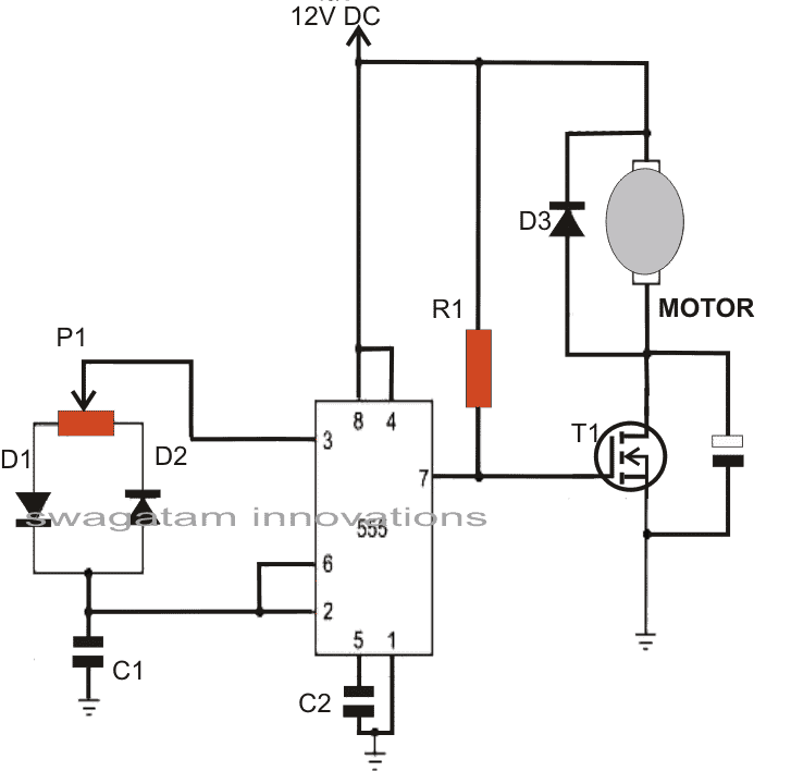
The following design shows the motor control module for the proposed single axis solar tracker which involves a simple circuit made from a cheap 555 IC and some other important semiconductor parts. Pot P1 should be mounted outside the enclosure in which the circuit may be covered.
P1 is the main component which may be used for adjusting the motor speeds during different seasons of the year such that the panel rotation remains more or less synchronized with the sun "movements".
In fact P1 may have to be adjusted very carefully such that the motor operates at some fixed speed.
The gear mechanism should be arranged such that the smaller gear and the larger gear diameters produce a constant angular movement to the panel in order to keep the panel face more or less perpendicular to the sun throughout the day.
The setting of P1 should be noted down each time the settings are refreshed corresponding to the different months of the year. This data may then be repeated for the future years.
Parts List
- R1 = 10K
- P1 = 220K
- D1, D2 = 1N4148
- D3 = 1N5402
- T1 = 30V, 10amp mosfet
- IC= 555,
- C1 = 5nF
- C2 = 10nF
- C3 = 100uF/25V

Comments
why amperage motor can be run on this. I plan on using the solar cell to power it and the motor uses about 3 amps. I see the mosfet will handle 10 amps.
The motor ampere will depend on the MOSFET rating. A 10 amp mosfet will be able to handle a 3 amp motor quite well.
Plz send me coding of motor…
And this project are running condition or not???
yes it is….
coding and estimation will need to be done by the user through some practical monitoring.
Please,pins erroneus scheme!!
it's configured differently, not in the usual format,
but it's correct.
you you wish you can change it to the standard format with pin#3 as the out
Hi Swagatam.
-I think it would be possible to make an even simple sun-tracker by having two photo-sensitive resistors (GL5516 or the like) connected in series between VCC and GND, with the center-point to basis of a single transistor/OpAmp, which would turn a DC motor forward or backwards.
The motor's voltage level would be centered 'above GND'. You probably get the idea. 🙂
The photo sensitive resistors would 'fight' eachother. When one gets less light than the other, the voltage level would be lower or higher than the center of the applied voltage.
GL5516 is 'dirt-cheap' on eBay; you get 20 for $1.
For myself, I think I'll be using the ARM microcontroller, as it will already be present in the circuit, measuring voltage and current.
Both GL5516 would be connected to one ADC-pin and the other leads from the GL5516 would be connected to a GPIO port.
Those port can be tri-stated (open drain) so I can measure one at a time.
I believe this simple system could be used for both the X and the Y direction.
The two photo-resistors could be mounted on some kind of wheel (or gear), almost next to eachother, and the wheel could be mounted on the tracker's panel-axis.
-You may use this idea in whichever way you like. I think it could be used for balancing other thnigs as well. 🙂
Thanks Pacman, yes I do agree with you, in fact I already have a similar circuit posted in my blog, you may check it out below for your reference:
https://www.homemade-circuits.com/2011/12/how-to-build-dual-solar-tracker-system.html