In today's world, the idea of control is strongly connected to the ability to use remote devices. Home automation, known as domotics, allows us to switch ON/OFF various things such as televisions, hi-fi systems, blinds, curtains, garage gates, and even the brightness of lights using a small control unit.
The signals for controlling these devices are typically transmitted using infrared frequencies, which are not visible to the human eye. A sophisticated coding system ensures precise and reliable commands.
The transmission of this information usually follows the RCS code, which uses a 14-bit word length and a carrier frequency of 36 kHz.
Using a TV Remote
Considering the wide range of TV remote control devices found in households, it's possible to use these signals to activate a different receiver that specifically responds to infrared radiation detected by a IR sensor-equipped surface.
A simple, inexpensive integrated component will suffice to detect the signal from any remote control button, as long as its carrier frequency is compatible with the chosen component.
The received code is not important; its mere presence triggers a bistable flip-flop that activates a power stage, either relay-based or solid-state, as is the case with our setup.
Therefore, constructing an infrared (I.R.) receiver will soon provide a reliable and cost-effective remote control system.
Circuit Description
There is no consideration here for security or a code to select among multiple commands.
It is clear that the purpose of this implementation should not interfere with the normal operation of your television or VCR remote control, as it could accidentally activate them.
With this restriction aside, all possibilities are conceivable since the receiver module's sensitivity allows for a range of several dozen meters.
The complete schematic is shown in the figure below.
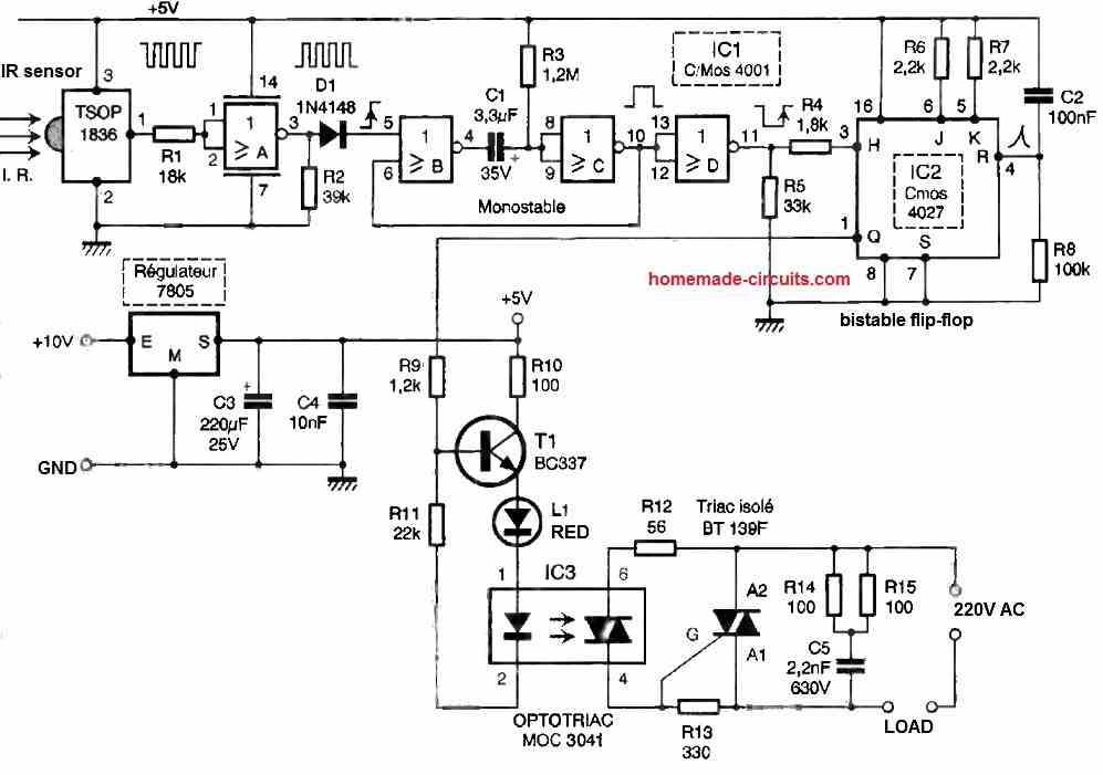
The photosensitive sensor is actually an integrated module for infrared reception, consisting of a PIN diode and a preamplifier. It also includes automatic gain control, a bandpass filter, and a demodulator.
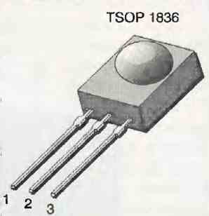
We chose the TSOP1836 model from the manufacturer TEMIC, which operates at a frequency of 36 kHz and comes in a specific three-pin package.
Since this sensor requires a 5V power supply, we have included a 7805 regulator along with filtering capacitors.
Regardless of which button is pressed on a standard remote control, it generates a negative-coded burst on pin 1 of the sensor.
It is not necessary to decipher the signal since we are only interested in the first negative edge.
The signal is inverted by the NOR gate A and then transmitted through diode D1 to the control input of a monostable flip-flop constructed using NOR gates B and C.
The positive pulse at the trigger input produces a pulse width of a few seconds to inhibit any other command or prolonged press on the remote control button.
By introducing an additional NOR gate as an inverter, we delay the moment when the unique rising edge of the signal can finally trigger the input of a bistable flip-flop.
As expected, we use the famous CMOS 4027 circuit, a dual JK flip-flop in master-slave configuration.
By connecting the J and K inputs of IC2 to a high level through resistors R6 and R7, each input pulse results in stable output behavior, similar to the operation of a well-known lighting time switch.
One pulse sets the Q output to 1, and another pulse resets it to 0.
It's worth noting that when the device is powered on, the capacitor C2, in conjunction with resistor R8, generates a brief positive pulse for reset, initializing pin 1 to a low level.
All that remains is to utilize the output of IC2. At this point, it is possible to activate a small relay through the transistor T1. Our preference leans towards a fully static power output.
We have included a red LED, L1, in series with one contained in a small optoisolator, such as MOC 3021 or preferably 3041, which includes zero-crossing detection.
The triac, without a heatsink, is capable of safely controlling several hundred watts at 230V.
Construction
The layout of the copper traces on the printed circuit board is relatively dense. Three bare wire jumpers are inserted first.
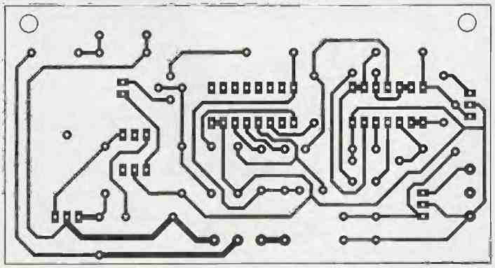
We recommend using a high-quality socket for mounting the integrated circuits, preferably tulip pins.
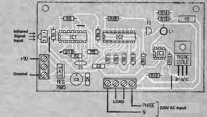
It would be wise to protect this setup by enclosing it in a suitable case, ensuring enough space for the 9V miniature battery for the detection and shaping part.
The sensitive side of the IR sensor should be exposed to infrared radiation and oriented towards it during installation.
If the response delay between the command pulse and the illumination of the red LED seems too long, the value of the electrolytic capacitor C1 can be reduced, but not below 680 nF.
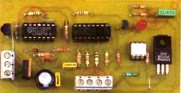
Tested Prototype Image


Comments
Hello sir,
i am really drawn towards this innovative idea and i would like to do this as my final year project at the university, does it require someone to have some knowledge of programming to successfully do this? and how much does the whole components cost if i am to buy them? eagerly waiting for your reply. thanks!
Hi Rwatis,
You don’t require any programming knowledge to build this circuit, but you must certainly be well versed with basic electronics and soldering skills.
Here’s another similar design which is much simpler than the above concept.
https://www.homemade-circuits.com/how-to-make-simple-infra-red-remote/
Let me know if you have any further questions, I will be glad to assist.
Thank you so much for your response, sir. The trouble is that I am a final-year university student, and I was assigned “intensity control using a tv remote” as my project topic since someone performed “switching the bulb on/off using a remote” as a project previous year, so they told I couldn’t redo the same project. I have some basic knowledge of electronics and soldering, and I really want to start with the first project, but I’m afraid about programming. I just want you to help me do this, and I will be so inspired to undertake more similar projects. Sir, could you please tell me how much money I will need to spend on components and how long it will take? waiting to hear from you. thanks
Thank you Rwatis,
Remote controlled intensity controller for a 220V AC or 120V AC incandescent bulb is not an easy project but i can suggest a PWM circuit.
This circuit will be complex with many test points and stages. And the bulb will be incandescent, not an LED bulb.
The cost will be around be around $5 US.
However, please note that if you get stuck in the middle of the project or can’t get the required results, i will not be able to to fix it for you, because I cannot check your circuit connections practically.
I can only help you to understand the stages and proceed with it.
Hi, sir. I appreciate your constant feedback.
Will the project for PWM be distinct? and if yes, how is it functioned? Thank you.
Thank you Rwatis,
Can you please elaborate what you mean by “project for PWM be distinct?”
Do you mean whether the results will be distinct?
Good evening Swagatam!
i was kind of confused when you talked of PWM( pulse width modulation), i thought it was for some other project other than intensity regulation, but I’ve understood now. I’m just requesting that you share with me the circuit diagram if possible. thanks.
Thank you Rwatis,
I will design it soon for you, and let you know.
Rwatis, you can check the design below, it can be used to control a 220V lamp using TV remote:
https://www.homemade-circuits.com/wp-content/uploads/2024/03/remote-controlled-light-dimmer-220V.jpg
thanks a lot sir!
hello sir
my question was, ” will the idea of PWM be used in intensity control? or you it will be used in a different function other than intensity control? thanks.
Yes, PWM will be specifically used for the intensity control.
Thanks for all; It’s really great.
Hello sir Swagatam good afternoon. The circuits were best before, because it were with colors, and better design. But now the circuits are black and white.
Thank you Carlos,
The above diagram was contributed by an external author, it is not designed or drawn by me, therefore it is black and white.