
Nowadays the CFL and fluorescent lamps are almost completely replaced with LED lamps, which are mostly in the form of circular or square shaped flat ceiling mounted LED lamps. These lamps beautifully merge with the flat ceiling surface of our homes, offices or shops providing an aesthetic look for the lights, along with a high […]
Lamps and Lights
LED Night Lamp with Dimmer Circuit
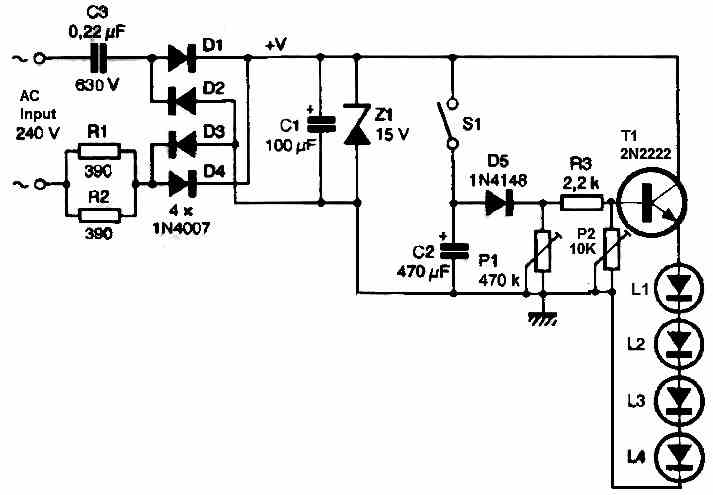
In this post I have explained a simple plug-in type night lamp circuit with delayed switch OFF and dimming facilities. The entire circuit is built using a transformerless power supply which ensures that the unit is very compact and can be plugged into any existing 220V mains AC socket. Circuit Description The electronic schematic of […]
220 V Slow Fade Bedside Lamp Circuit
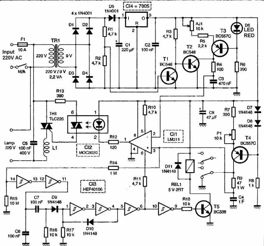
The operating principle of this children’s night light is to gradually familiarize the child with darkness by gradually reducing the brightness of their bedside lamp. The room’s brightness will slowly fade away and completely extinguish after a duration ranging approximately between twenty minutes and 5 to 7 hours. This duration can be adjusted from week […]
Electronic Candle Flame Simulator Circuit
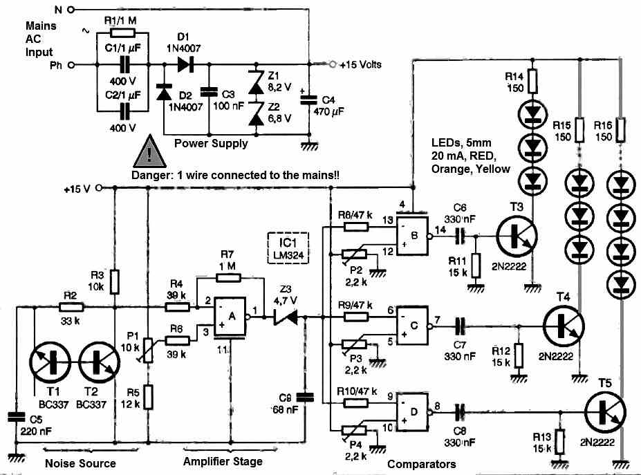
This electronic candle accurately imitates the flickering flame of a lit wick, but it remains considerably cleaner, doesn’t drip, and poses no risk of setting your interior on fire. It only requires a handful of ordinary components and is powered directly from the mains with minimal energy consumption. Its lifespan will be exceptionally long. How […]
Glittering LED Flower Circuit [Multicolored LED Light Effect]
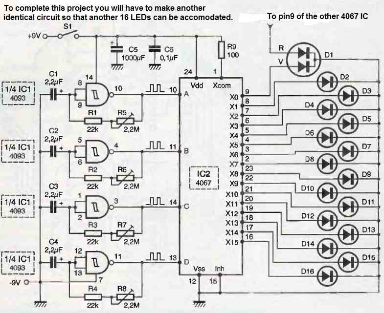
The glittering LED flower circuit we are presenting here holds significant importance in our artistic city and offers no particular interest other than delighting your view with various multicolored and varied light effects. This luminous LED flower is also unique in its design, allowing ample room for everyone’s creative sense. The goal is to control […]
LED Chaser using IC 74C164: 8 LEDs turn ON one by one, Shut off, then Repeat
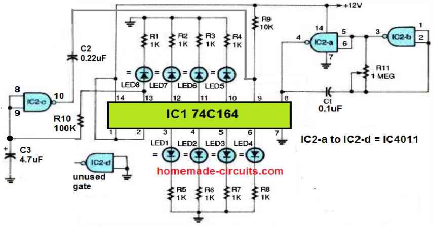
Referring to the following chaser circuit diagram below, we can see a low-frequency, astable oscillator circuit, made up of two gates, IC1a and IC1b, from the IC 4011 quad two-input NAND gate. The operating frequency of this astable is determined by the values of C1 and R11. This circuit configuration works well as a clock-pulse […]