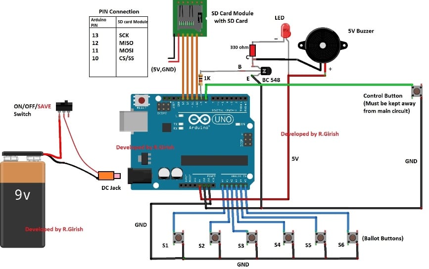
In this post I will show how to construct a circuit for an Electronic Voting Machine using Arduino and SD card module where the election data is stored in the SD card. UPDATE: This circuit has been upgraded to an improved version in which the results can be viewed over an attached LCD display, you […]
Newly Updated Circuit Projects:
SMS Based Water Supply Alert System
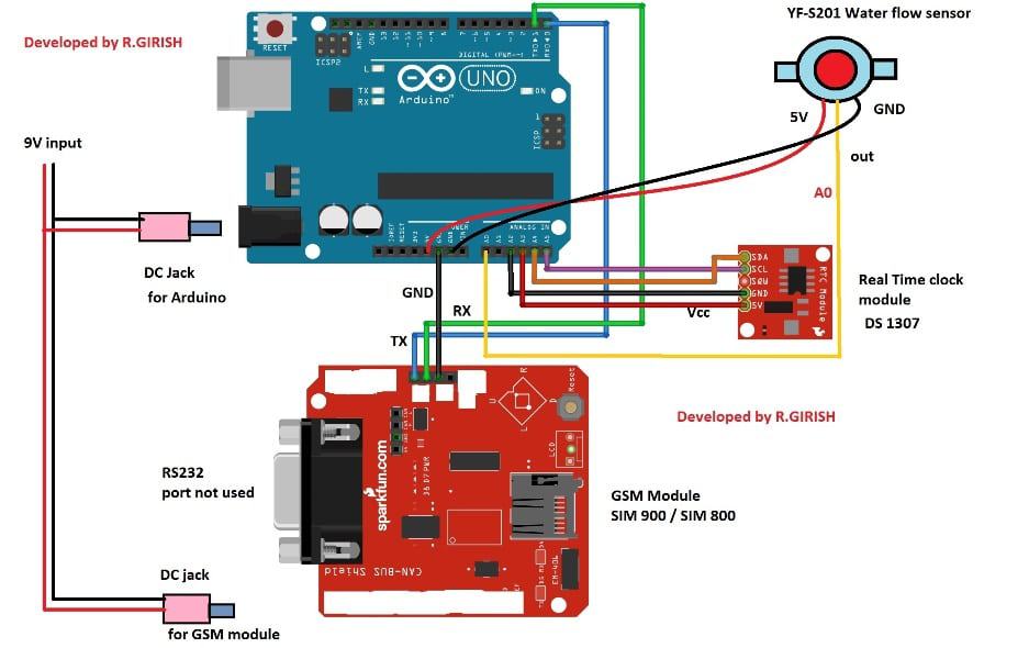
In this post I will show how to construct a circuit which will notify the user via SMS if the water supply to you area / home is initiated. It can show the time when the water is begin to supply and ended, average water flow speed in liter per minute and total water delivered […]
Vehicle Speed Detector Circuit for Traffic Police
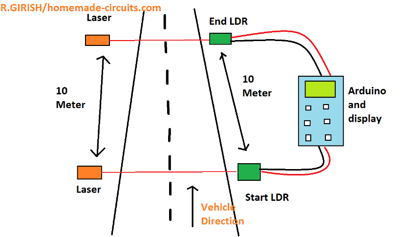
In this post I will show how to construct a circuit which can measure the speed of any vehicle on roads and highways. The proposed circuit is kept stationary at a place where the vehicles are suspected to over-speed. If any vehicle goes beyond the speed limit, the circuit alerts immediately. We will be looking […]
Converting Analogue to Digital (Analogue Read Serial) – Arduino Basics
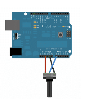
In this Arduino basics I have explained the code implementation procedure wherein an external analogue signal is fed to the Arduino analogue input and translated or converted into a correspondingly proportionate digital readout. Here we employ a variable resistance in the form of a pot as the analogue signal source. Analog Read Serial In this […]
Blinking an LED with Delay – Arduino Basics
Here I have explained the bare minimum code for compiling an Arduino and also the method of blinking an LED using an Arduino board. Learning the Bare Basics Here we discus and try to understand the fundamental minimum code that one would need to compile an “Arduino Sketch” which consists the setup()method and the loop()method. […]
Arduino SPWM Generator Circuit – Code Details and Diagram
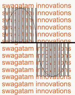
In this post I have explained how to generate sine wave pulse-width-modulation or SPWM through Arduino, which can be used for making a pure sine wave inverter circuit or similar gadgets. The Arduino code is developed by me, and it is my first Arduino code, …and it looks pretty good 🙂 What is SPWM I […]