In this article I have explained how to build a simple AC ammeter circuit which can be used for checking the current consumption of household 220 V or 120 V appliances.
The main reason for high monthly utility bills is the use of large electrical equipment like refrigerators, washers and dryers, dishwashers, etc.
These appliances which were previously cutting-edge and energy-efficient start consuming more and more energy as they get older.
One method of saving electrical expenses is to utilize large appliances less frequently. However, intermittent usage of appliances like refrigerators and freezers may not be simply acceptable.
To find out which appliances are responsible for your high electricity bills, naturally, you go for your trusted multimeter. But you realize that the meter's AC current range is restricted to a few milliamps.
Because high-wattage resistors are needed to implement AC amp measurement, smaller multi-meters are not designed to detect large amounts of current.
Warning: The circuit I have explained below is not isolated from AC mains and is therefore extremely dangerous to touch in an uncovered and switch ON condition. Appropriate caution is strictly recommended while using or testing this equipment.
Circuit Description
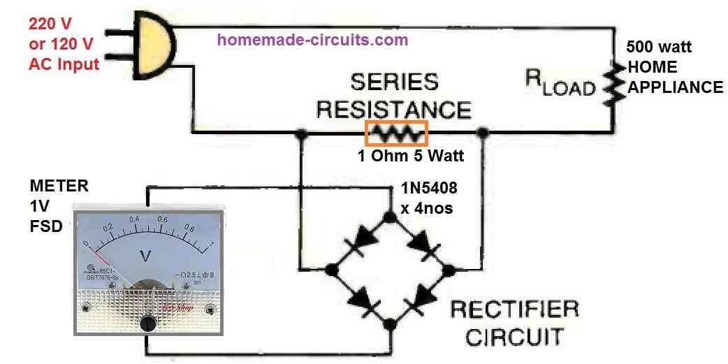
The figure above depicts a fundamental ammeter circuit. A resistor (R) is connected in series with the load within this circuit.
The series resistor must always be connected in series with the load and accept all current delivered to it.
According to Ohm's law, a voltage drop is created when current flows through a resistance.
This voltage drop that develops across the resistance is precisely proportional to the current that flows through it.
Now, remember that all voltmeters, including AC ones, display readings in DC only.
This means, before the input AC signal could be fed to the DC meter, it needs to be rectified to DC so that the ammeter can read it.
To create a fair representation of the current flowing through it, the series resistor needs to drop the voltage sufficiently.
Also, the power rating of the series resistor should be as small as possible. The resistor value should be also small enough so that most of the voltage is dumped across the actual load.
Calculating the Resistor Value
As an illustration, let's imagine that our circuit has a series resistance "R" of 1 ohm and a current "I" of 1 amp flowing through the load.
The voltage drop (E) across the resistor will be as follows according to Ohm's law:
- E = I x R = 1 (amp) x 1 (ohm) = 1 (volt)
- Using Ohm's power law (P = I x E), we get:
- P=1 x 1=1 watt
- From the above calculation we can assume that if a 220 V, 1 amp load is appliance is used, then a 1 Ohm series resistor would drop around 1 Volt across it.
Now suppose if the load is a refrigerator of 500 watts, with a supply voltage of 220 V.
In this situation, the current passing through the resistor would be 500 / 200 = 2.27 amps
Again, solving the Ohms law we can calculate the resistor value to get an optimal 1 V drop across it.
- E = I x R
- 1 = 2.27 x R
- R = 1 / 2.27 = 0.44 ohms,
- wattage or the power of the resistor would be P = 1 x 2.27 = 2.27 watts or simply 3 watts.
However there's one problem.
Since our circuit utilizes a bridge rectifier for converting AC voltage across the resistor into a DC potential, we always have two diodes in series for each AC cycle.
Now, because each diode will drop 0.6 V, a total of 0.6 + 0.6 = 1.2 V would be dropped through these diodes.
Therefore, to get an effective 1 V across the meter, the resistor must be able to develop a potential drop of 1 + 1.2 = 2.2 V.
Returning back to our previous calculation, the series resistor value for a 500 watt appliance now would be:
- R = 2.2 / 2.27 = 0.96 Ohms.
- Power = 2.2 x 2.27 = 4.99 watts or simply 5 watts.
This implies that, to measure the current passing through a 500 watt appliance, the series resistor in our AC ammeter circuit must be rated at 0.96 Ohms and 5 watts.
In this way the series resistor value can be appropriately calculated for measuring the AC current across any given appliance.
Parts List
The parts required for building a simple AC Ammeter circuit is given below:
- Resistor 1 Ohm 5 watt = 1 no
- 1N5408 diodes = 4 nos
- Two-in plug = 1 no
- 1 V FSD moving coil meter = 1 no
- 3 pin socket for the load = The R(load) in the diagram can be replaced with a 3-pin socket for plugin in the desired load.


Comments
If you put the series rezistor to dc side, you can measure more efficiently and reliable..
DC supply is for the meter, so the load current sensing resistor cannot be connected with the DC supply…
Are you sure… Think once again..(no think.. Make it and try) . Because you are posting.. I am using it. 🙂
Yes, I am sure, the circuit diagram is correct as given in the above article…
The voltmeter will not show anything until the diode conduction voltage exceeds 2×0.65v. This is the problem with the circuit. If you place the resistor on the dc side, you will prevent this conduction voltage blindness. Instead of insisting on your circuit, try it and see.
The circuit is intended to detect high current, so anything below 1.2V would be very small current, which can be ignored.
How do we place the resistor on DC side??
Ammeter not shown in the diagram but a voltmeter
The voltmeter shows the equivalent amount of current consumed by the load.