This flashlight triggered burglar alarm circuit will instantly switch ON an alarm as soon as it detects light from the burglar's torch or flashlight.
Burglars and thieves normally set out to steal or rob during nights, when it is completely dark, and depend on a flashlight to investigate the area.
Our circuit is setup and activated in the area which needs to be protected.
As long as it is dark, the circuit remains switched off. If in case a burglar tries to investigate the area with his flashlight ON, our circuit detects the light from his flashlight and sounds the alarm.
Once the alarm is triggered, it gets latched and can be deactivated only by powering it off.
Circuit Description
As can be seen in the following diagram, the trigger circuit consists of a couple of transistors, configured as a latch.
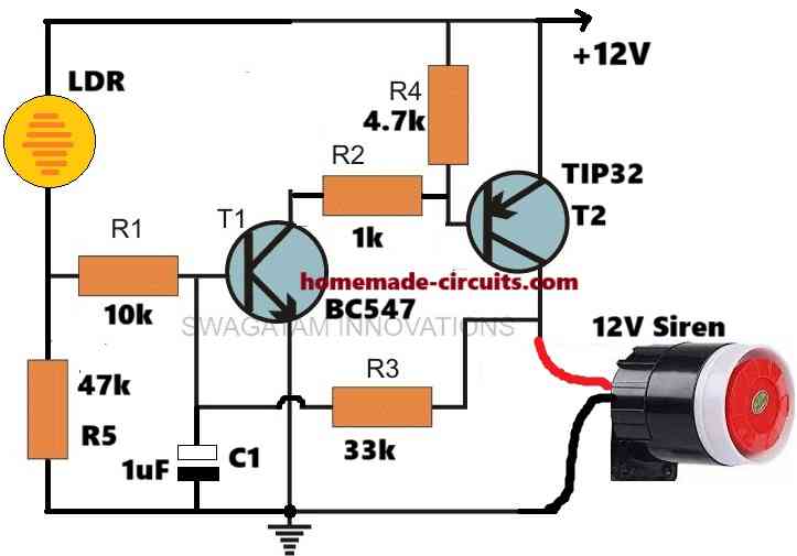
The feedback loop through R3 is very crucial as it becomes responsible for implementing the latching operation as soon as an input trigger signal is detected.
Initially, while is completely dark and power switched ON, the circuit stays in its standby mode. In this position The LDR resistance is very high, at around 5 to 10 meg Ohms.
Therefore, T1 is unable to get any base bias, and remains switched OFF. With T1 in switched OFF condition, T2 also remains switched OFF, and keeps the siren shut off.
Now suppose a burglar or an unwanted guest arrives at the location with a flashlight and tries to investigate the area with its flashlight ON.
In this situation, as soon as the flashlight light happens to fall on the LDR, causes the LDR to resistance to drop drastically, which is enough to turn ON T1 momentarily.
Even a millisecond switch ON for T1 is enough to turn ON T2 and latch the circuit in that position.
The above latching of the circuit also turns ON the siren which starts blaring loud, alerting the owner regarding a security breach.
The siren can be turned OFF only by switching OFF power to the circuit.
Parts List
- All Resistors are 1/4 watt CFR
- 10k, 47k, 33k, 1k, 4.7k = 1 each
- LDR (any standard) = 1
- Capacitor 1uF / 25V Electrolytic = 1
- Transistors, BC547, TIP32 = 1 each
- 12V Siren = 1
Have any related questions or doubts? You can jot them through the below given comment box.


Questions & Answers
Hi Swagatam.
I aleady have a doorbell transmitter and receiver. I wondered if I could use this setup combined with a PIR solar powerd LED motion detector to transmit a signal to the bedroom at night to alert me to any potential intruders outside our gate.
I therefore used the positive and negative wires going to the LEDs as as a signal source to the doorbell transmitter. I connected the collector and emmitter pins of an NPN transister across the 3V doorbell battery holder together with a base transistor. Positive wire from LEDs goes to the base.
It worked, but the LED light is on for 15 seconds resulting in a constant annoying ding-dong sound from the receiver in the bedroom. I needed just one short duration monostable pulse so I put a small 103? ceramic capacitor and resistor in series with the base transistor wire and now it works perfectly. It seems the capacitor fully self discharges in approximatly 60 seconds which is longer than the LEDs are on, provided there are no futher inputs.
The alarm now only sounds once once the solar light is activated.
Thought you might be interested in this “hack”
Kndest regards
John Renwick
Thanks so much John, for this innovative idea.
I will surely consider using this hack in one of my related future articles.
I am sure the readers will find this idea very useful.
Adapting PIR solar powered LED light to transmit signal to receiver