This security alarm circuit using RCWL-0516 microwave radar motion sensor will detect any moving thing in the restricted area and turn ON an alarm sound.
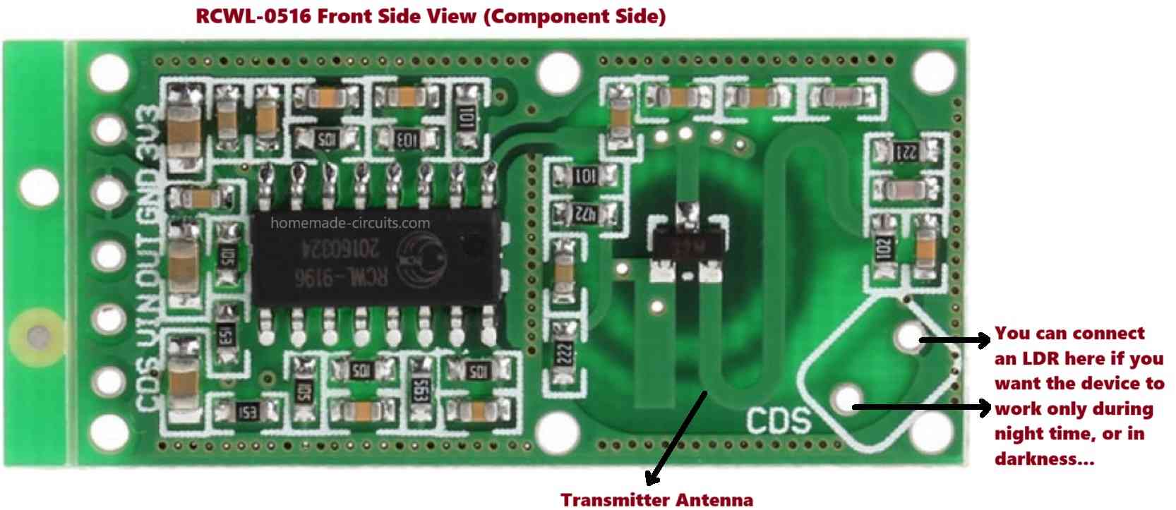
The RCWL-0516 is basically an advanced motion sensor using microwave radar signals.
I have already discussed the working of RCWL-0516 elaborately, which you can read for more details.
Circuit Description
The following figure shows the full circuit diagram of the proposed security alarm circuit using RCWL-0516 microwave radar motion sensor.

Referring to the above figure, the working of the circuit can be learned from the following points:
The circuit operation is actually very straightforward, thanks to the outstanding RCWL-0516 motion sensor module.
As we know that the RCWL-0516 module will detect anything that moves within its detection range and in response produce a positive voltage at its OUT pin.
Therefore as soon as a potential intruder or burglar tries to trespass the restricted zone, it is quickly detected by the RCWL-0516 module.
This causes the RCWL-0516 "OUT" pin to generate a positive voltage which is sent to the base of the TIP122 transistor via the 4.7k resistor and the LED.
The LED lights up, and the TIP122 switches ON turning ON the alarm device.
The alarm starts sounding indicating a possible intrusion in the protected zone.
If you want the circuit to be functional only during nighttime or in darkness, you can add an LDR on the back side of the RCWL-0516 module.
Whenever an intruder is detected, the RCWL-0516 module keeps the siren activated as long as the intruder movement is detectable in the area. It shuts down the siren after a delay of 2 seconds once the moving object is terminated from the detection zone.
Parts List
- Resistors are 1/4 watt 5% CFR
- 4.7k = 1
- 10 ohm = 1
- Semiconductors
- Transistor TIP122 = 1
- RED LED 3.3 V, 5mm, 20mA = 1
- Diode 1N4007 = 1
- 12V Siren Module = 1
- RCWL-0516 module = 1
- 12V 1 amp Power supply SMPS = 1


Questions & Answers
Please give the calculations of 4.7 k and 10k resistances. What is the use of 10 k resistor in the circuit.
Both the resistor values are not critical, the 4.7k value must be such which allows minimum glow on the LED. It can be calculated using the formula:
R = (5 – 3.3) / 0.02
The 10k pull-down resistor is also not critical, its value must be such that it allows at least 1.5 volts at the base of the TIP122
The output of rcwl 0516 is 3.3 volt and not 5volt so R will be 3.3 -1.8,because forward voltage of red led is 1.8 volt not as mentioned you. Please clarify. Also tell us the base current and collector current of tip 122.
Thanks for the correction, I mistakenly assumed the output to be 5V.
I have corrected the diagram according to 3.3V output.
The LED must be 3.3V 20mA type.
No resistor is required for the LED, although you can use a 10 ohm series resistor for better safety.
For calculating base resistor for TIP122 you can use the following formula:
R = (3.3 – 1.2) * hFE / Siren current
hello sir، hope all is going well، sir what is the alternate of tip 122?
ok sir, i will try and update you….
thanks
Thanks Ghulam, I am good!
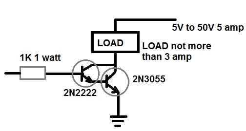
There’s no direct replacement for the TIP122 transistor, but you can easily replicate it using a TIP131 and 2N2222 in a Darligton configuration..
if 10 ohms is used, base current will increase. for proper base current 1k resistor should be used with 5 volt output from rcwl 0516.
The logic high from the OUT pin is 3.3V, so 10 ohms is fine for the LED, considering the LED fwd V is also rated at 3.3V.
You can use the formula for calculating the resistor value.
1k can be also used if the LED is high bright type.