In this post I have explained a simple wireless LED light circuit which can be used for automatically switching ON LED lights for illuminating paintings during night time. The indoor lights are connected to a 433 MHz wireless receiver unit, while the transmitter is installed outdoors.
When sun is down, the transmitter is switched ON through a darkness activated relay and a battery.
The signal from this 433 MHz transmitter then turns ON the indoor receiver module wirelessly to switch ON the LED lamp for illuminating the indoor painting.
The ON/OFF sequence is completely automatic, designed to repeat the cycle daily without any human intervention.
The transmitter is powered by a chargeable battery, charged through a solar panel. The 433 MHz receiver unit is also powered by a battery which can be charged from house AC mains outlet.
The circuit idea was requested by Mr. Carlos, as given below:
Design Request and Specifications
I’m trying to make a circuit that illuminates an indoor painting at night for 14 hours. Starting at 6:00 p.m. and turning off at 8:00 hrs.
The lighting is with LED, it must be activated with LDR when capturing the darkness outside and sending a signal with RF 433MHz and turned off when capturing the light by sending a signal to the receiver.
The transmitter must be outside the house powered by a solar cell that recharges a battery that does not consume much current and inside the receiver with a rechargeable battery, this process is daily.
Using 433 MHz Transmitter Receiver Modules
For the proposed automatic darkness activated 433 MHz wireless lighting circuit, we will need a readymade one channel 433 MHz transmitter/receiver modules as shown below.
These units can be then further configured with relays for the intended operations.
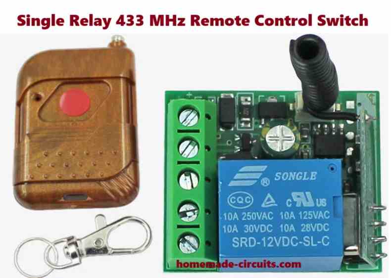
The left side unit is the wireless transmitter module with a single push button.
The right side unit is the wireless receiver module with a single relay. The relay is toggled ON/OFF whenever the user presses the red push button on the transmitter module.
Both the modules are designed to work with 433 MHz frequency within a range of 100 meters.
Transmitter Module Configuration
As per the requested specifications, the 433 MHz transmitter module needs to be switched ON automatically during night time.
It also needs to have a battery to keep the transmitter module powered so that it can send a continuous wireless signal to the receiver module throughout the night, until morning.
The receiver module is supposed to respond to this wireless signal and keep the LED lamp turned ON every night for illuminating the paintings.
The transmitter battery needs to be charged during day time through a solar panel, so that it can keep the transmitter module continuously powered daily night.
The following circuit design fulfills the above specifications perfectly.
Circuit Description
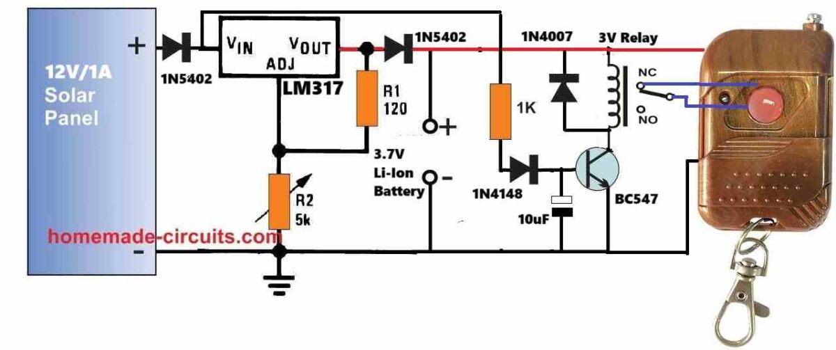
As shown in the above figure, a solar panel is used to supply the DC voltage to the entire circuit.
The 12V from the solar panel is appropriately regulated to 4.2V by the IC LM317 voltage regulator for charging the battery with a constant voltage.
This must be precisely adjusted using the preset R2. For ensuring better safety and avoid any possibility of overcharging, the maximum voltage across the battery points may be adjusted to 4.1V.
The relay driver stage is built using the transistor BC547. The base of the transistor is connected to the solar panel output.
It means, the transistor will remain switched ON until the solar panel voltage drops below 0.6V, which can happen only when it is significantly dark outside or almost nighttime.
The above feature eliminates the need for an LDR sensing of the day night conditions.
During daytime or until dark, the transistor BC547 remains switched ON, and therefore the relay also remains switched ON.
Due to this, the switch of the transmitter is held switched OFF condition, or disconnected by the N/O contacts of the relay.
Now, when darkness sets in, and the solar panel voltage drops below 0.6V, the BC547 transistor turns OFF. This causes the relay to switch OFF and its contacts changeover to its N/C points.
Since the N/C contacts of the relay are configured with the push button of the transmitter module, the transmitter is now switched ON.
The transmitter now starts sending the 433 MHz signal to the receiver module.
The receiver module responds to the above signal and turns ON the LED lights for illuminating the painting.
Receiver Module Configuration
To ensure the LED light are automatically turned ON as soon the wireless signal is received from the transmitter, the receiver module must be configured in the following manner.
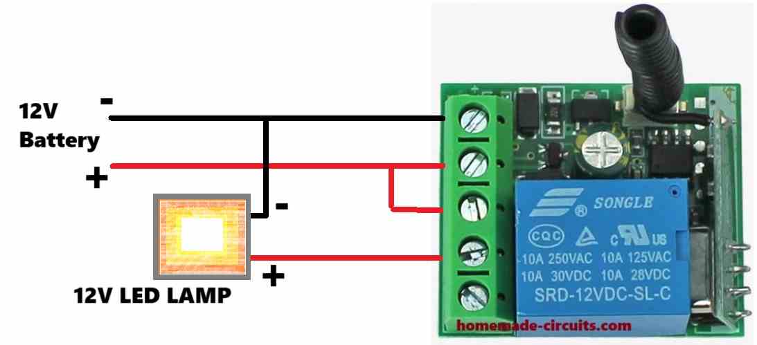
The 433 MHz receiver module configuration looks pretty simple, and just needs to be wired as shown in the above diagram.
Here, the 12V positive DC supply is connected to the positive terminal of the LED lamp through the N/O and the pole contacts of the receiver module relay (blue relay).
The negative of the LED lamp is connected directly with the ground of the supply input.
At nighttime, when the outdoor transmitter module switches ON, the receiver module responds to its signal and turn ON the blue relay, which finally turns ON the LED lamp.
This concludes our article on automatic night activated wireless LED light circuit, if you have any related questions, please feel free to ask through the comment below.

Questions & Answers
pls help ,
I need a simple power transmitter and receiver circuit, to power 2/3 bulb wireless at a small distance
Sorry, there’s no simple RF based Tx, Rx circuit which is possible..it will be relatively complex.
Buenos días, le agradesco su atención con el diagrama que me envió, lo tomaré para probar en la idea que tengo, muchas gracias por su ayuda.
You are most welcome, let me know if you face any problems with the circuit…
Good evening, I am Mr. Carlos Velazquez. Some time ago I was supported by a lighting project for paintings with a solar cell.
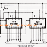
In this case, if it is not too much trouble to guide me with a stepper motor to start it on a base that moves it back and forth, but without programming and either with a limit switch or another option that turns certain turns to stop it, I will give you the motor data.
Voltage 2.8, amps 2.0, resistance/face(ohms) 1.40+-10%, inductance/face 3.00+-20%, holding torque 0.59(5.22), step angle 1.80.
I would appreciate it if you could describe the process to study it well. Thank you.
Hello Carlos,
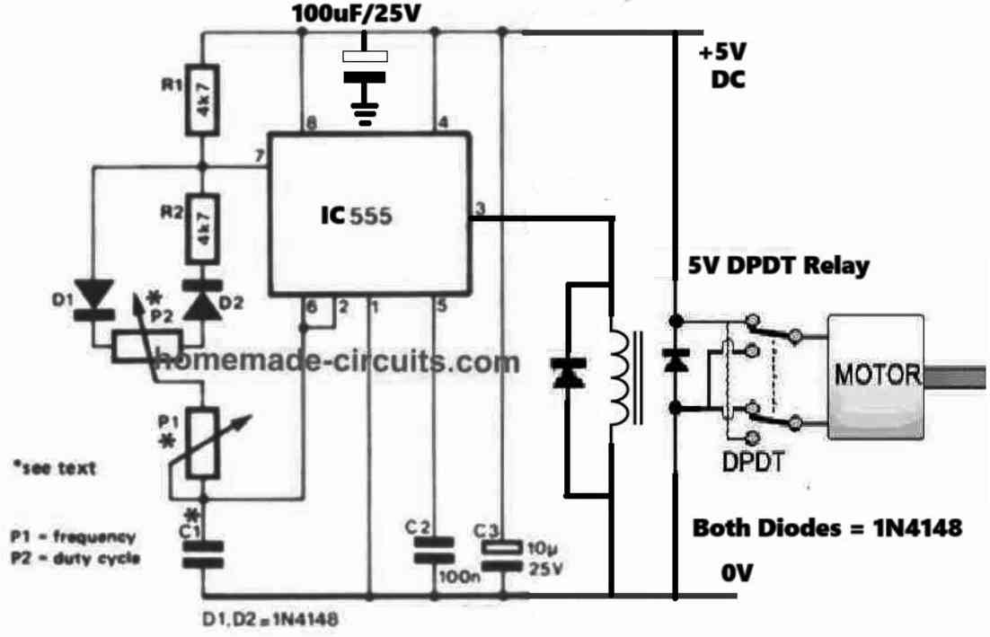
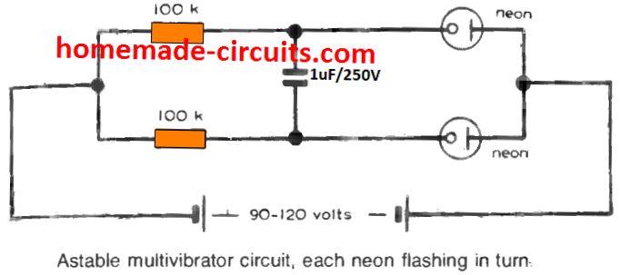
I do not have a circuit for a stepper motor with reverse-forward operation.
However, the following circuit below can be used with any ordinary DC motor for achieving the desired results:
Let me know if you have any further doubts or questions.
Buenos días, recibí el diseño y procederé a realizarlo, le agradesco su tiempo y dedicación por apoyarme. Gracias.
Hay alguna forma de yo poder apoyarlo en algo por su tiempo y trabajo?
No problem at all, I am glad to help! You can support my site by Bookmarking it!
Let me know if you have any further problems or doubts regarding the circuit.
Disculpe la pregunta, en donde lo hago para marcarlo como favorito.
In the URL bar at the top, on the right end you will see a star, just press that star, the entire site will get bookmarked.
Esta bien, en cuanto consiga los componentes y lo arme le informaré sobre el comportamiento y función.
Seguimos en contacto Mil gracias.
Sure, no problem, all the best to you!