Feeling difficult to grope for a light switch in deep sleep when someone calls you at night? Then may be this cellphone triggered RF night lamp circuit can solve your problem....This is a very simple basic circuit and is easy to construct compared to other online available circuits which switches on a relay when it detects a cellphone RF signal.
USES:
This circuit can be fixed in your bedroom and switch it on during night times so that when it detects an RF signal from cellphone, it switches on a relay and hence easily enabling the user to reach his mobile which might be kept away from bed and also enables him to easily write down any important information given by the caller.
CIRCUIT DESCRIPTION:
This circuit detects any RF signal within its vicinity (8-10 metres). Place it near the switch board and connect the relay contacts to the light bulb and it aids you to reach your mobile during nights......
Here instead of using a single transistor(like 2N4403), we used a darlington pair of BC516 transistor and hence the sensitivity of the circuit is increased to the maximum extent......
You can use a 30 inch long single cored wire as antenna if telescopic antenna is not available.
A high value capacitor C2 is added to the relay contacts which makes sure that the relay is not triggered immediately due to some false RF signal but only after making sure the signal is genuine (i.e., the RF signal should be present for few seconds before firing the relay) .
When power is applied to the relay contacts, initially, the capacitor is filled up with the charge and hence serving as a time delay. If the power is applied due to false RF signal, then the capacitor charges and discharges preventing the relay from triggering.
INSTALLATION SUGGESTIONS:
Solder the components on a general purpose PCB and keep the entire assembly in a plastic casing. Make sure to solder the relay on small PCB piece and keep the relay away from the circuit in the same plastic casing (as it switches mains AC). Connect the circuit to mains power and light bulb carefully and stick it above the switch board. And the antenna wire should come out from the casing.
AND INCLUDE A SWITCH FOR MAINS POWER SUPPLY SO YOU CAN SWITCH THE CIRCUIT ON DURING NIGHT TIMES. The circuit can work on any voltage from 6-12V. But make sure to use a relay that matches the voltage of power supply and the relay contacts current rating must match the bulb’s current rating.
Written and Submitted by: SS kopparthy
Circuit Diagram

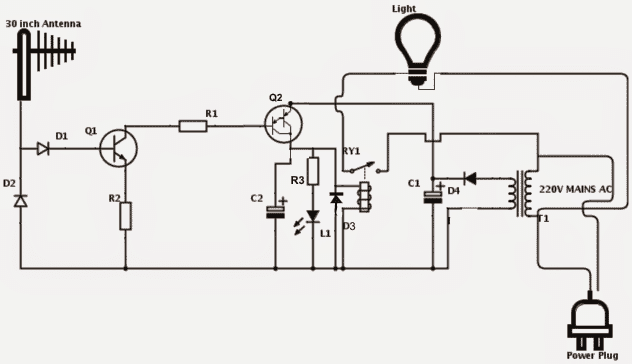
PARTS LIST:
- Q1 - 2N4401,
- R1 – 10K,
- R2 – 2.2K,
- R3 – 470ohms,
- D1, D2 – 1N34 germanium diodes,
- Q2 – BC516 darlington pair,
- L1 – GREEN LED,
- D3, D4 – 1N4007,
- C1 – 1000uf, 25V,
- C2 – 3300uf, 25V,
- RY1 – (as per DC voltage rating),
- T1 – 12V, 500ma transformer ,
- Antenna - 30 inch long Telescopic antenna or 30 inch long single cored wire.
sir what is the function of the led?
LED is simply to indicate the switch ON condition of the relay….
sir can you help me do the layout of this circuit? I badly need it. Please. Thanks a lot
sorry vduani, a PCB layout may not be possible at the moment.
if bc516 is not availble, what can i use please?
you can try using two BC557 connected in Darlington mode…
What of if their is no in34