The basic function of a comparator circuit to compare two voltage levels at its input pins and produce an output to show which input voltage has higher potential than the other.
In this article we will elaborately learn how to correctly design comparator circuits using popular ICs like IC 741, IC 311 and IC LM339
Difference Between a Comparator and Op Amp
The IC 741 is an ideal example of a single op amp, and the IC LM311 can be considered a good example of a dedicated single comparator.
You will find both these units having an identical "triangle" shaped device symbol internally, which we normally recognize and use for drawing comparator circuits. However, the output response of these two forms of comparators may have a few major differences.
Although an op amp and a comparator both can be configured to compare differential signals at their input pins, the main differences between the two counterparts are:
- In powered condition, the output of an op amp will be either positive or negative, depending on the input pin voltage levels, but can never be open. In contrast, a comparator output can be either open or grounded (negative), or floating.
- An op amp output can work without any pull up or pull down resistors, but a comparator will always require an external pull-up or pull down resistor to enable the output stage to work normally.
- An op amp can be used to build high gain amplifier circuits, a comparator cannot be used for such applications.
- The output switching response of an op amp is usually slower compared to a comparator IC.
A classic comparator circuit design can be seen in the following figure:
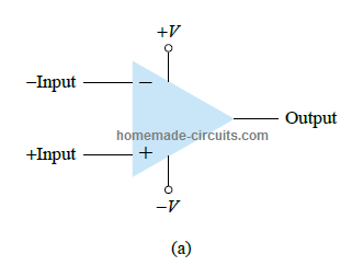
Here, the output responds with a "high" digital signal, whenever the voltage at the non-inverting (+) input is higher than the inverting (-) input. Oppositely, the output into a turns low digital signal, whenever the noninverting input voltage is lower than the inverting input voltage.
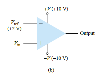
Referring to the above figure above, we can see a standard connection of a comparator circuit having one input (the inverting input in this example) configured with a reference voltage, and the other input pin which is the noninverting input connected to an input signal voltage.
During the time Vin is held at lower voltage than the reference voltage of +2 V, the output stays low at around -10 V. If Vin is increased just above +2 V, the output instantly changes state, and turns high to around +10 V. This change of state at the output from -10 V to +10 V indicates that the Vin has become higher than the reference +2 V.
The main component inside any comparator is an op amp circuit, which set at a very high voltage gain. To study the working of a comparator accurately we can take the example of the IC 741, as shown below:
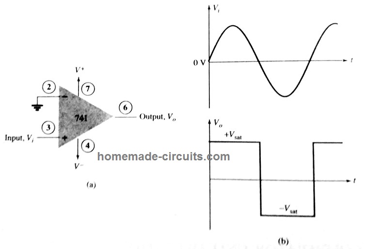
Here we can see the inverting input pin2 (-) is referenced to ground, or a 0 V level. A sinusoidal signal is applied on pin3 which is the noninverting input of the op amp. This alternately varying sinusoidal signal causes the output to switch between high and low output states, as indicated on the right side of the image.
When the input Vin moves even a millivolt over the 0 V reference, the difference is amplified by the internal high gain op amp of the IC, causing the output to go high at the output positive saturation level. This condition is sustained for so long as Vin signal stays above the 0 V reference.
Now, as soon as the signal level drops a shade below the 0 V reference, the output is driven to its lower level of saturation. Again, this condition is maintained as long as the Vin input signal stays below the 0 V reference level.
The above explanation and the waveform presented in the image clearly indicates the digital response of the output for a linearly varying input signal.
For normal applications, the reference level doesn't have to be at 0 V, rather can be any positive level as per the requirement. And, in case required the reference can be also connected either to the positive or the negative supply lines, while the input signal is applied at the other input pin.
Using IC 741 as a Comparator
In the following example I have explained how to effectively use an op amp as a comparator
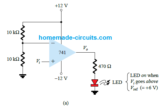
In the figure we can see an op amp circuit working with a positive reference set at its inverting input pin (-). The output is attached with an LED.
Using the voltage divider network formula, we can calculate the refernce voltage value on the (-) input pin of the IC.
Vref = 10 k / 10 k + 10 k x +12 V = +6 V
Since this reference is associated with (-) pin of the IC, if the voltage Vin at the (+) input goes higher than this reference or becomes more positive than the reference, will force the output Vo to switch to its positive saturation level.
This will cause the LED to illuminate, indicating that Vin has become more positive than the reference level of +6 V.
Oppositely if the noninverting input (+) is configured as the reference pin and Vin applied to the inverting input (-) pin, the output will go low as soon as the Vin input goes below reference value, and vice versa.
This will instantly cause the LED to shut off.
Therefore, the LED can be made to switch ON or OFF for a given input signal, by appropriately wiring the inputs pin with the reference level and the input signal.
Using Specialized Comparator IC Units
Normally op amps work great as comparator circuits, but using a dedicated comparator IC works even better than an op amp for a comparator application.
Comparator ICs are specifically ideally designed for comparator function and show an improved response such as faster switching at the output between the positive and negative levels.
These ICs possess higher immunity to noise, and on many occasions the outputs can be directly used for driving a load.
I have explained about a couple of popular comparator ICs in detail, from the following discussion.
Comparator Circuit using IC 311
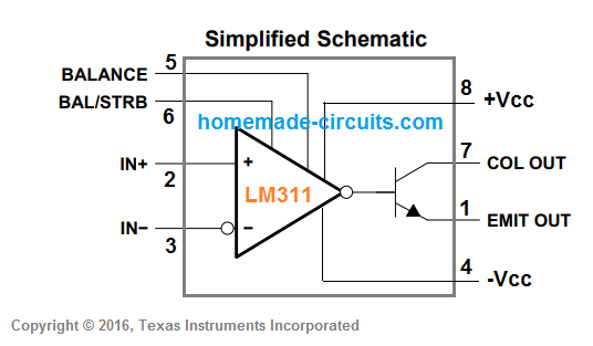
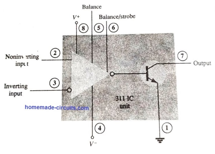
The figure above shows the internal layout and the pinout details of the comparator IC 311. The IC is designed to operate from a dual power supply also, in the range of +15 V and -15 V, which is a standard compatible level for all modern digital ICs.
The output stage inside the IC has a bipolar transistor, having floating collector and emitter terminals. This means that the output from this transistor can be configured can be configured in two different ways:
- By adding a pull-up resistor with the collector pin7 and grounding the emitter pin1, and subsequently using the collector as the output.
- By joining the collector with the positive line and using the emitter as the output.
The transistor output can be also used for driving a relay or a small load such as a lamp directly without any external buffer stage.
The IC also features a balance and a strobe input which can be gated with the output.
We'll discuss a few useful applications of this IC in the following sections:
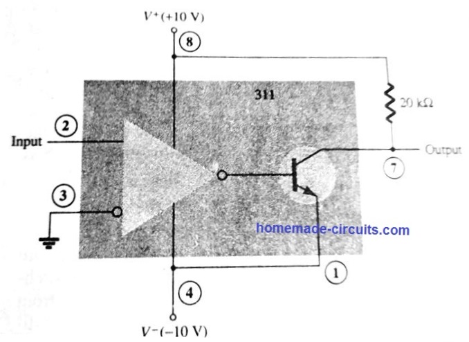
The figure above shows how the IC 311 can be configured like a zero-crossing detector comparator to sense the input voltage, whenever it crosses the zero line.
The inverting input (-) of the 311 can be seen joined with the ground. During the period the input signal is at the positive level, the output transistor remains switched ON, which creates a low (-10 in this example) at the output (transistor collector).
As soon as the input signal goes negative or below 0 V, the transistor is turned OFF. This creates a positive +10V at the collector output of the IC. This allows us to know when the input signal is above the zero level and when it has dropped below the zero level.
The next figure below shows how IC 311 comparator can be used for making a strobed circuit.
In this comparator circuit example, the output pin7 will turn high when pin3 voltage level rises above pin2 reference. But this can happen only while pin6 strobe input pin is low or at 0 V.
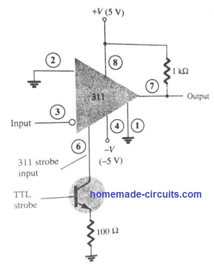
When a high TTL strobe is applied at the base of the transistor, pin6 becomes low, causing the IC output transistor to switch off, and thereby enabling pin7 to go high.
The output continues to be high as long as the TTL input is held high, regardless of the input signal condition at pin3.
However, if the TTL signal is applied in strobed form, then the output responds to the input signal at pin3. Put simply, the output remains locked at high, unless pin6 is strobed.
How to Connect a Relay with a Comparator
The next figure below shows how comparator 311 can be used directly to operate a relay.
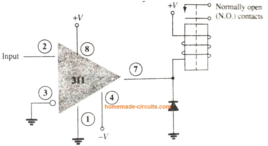
Here, when the voltage level at input pin2 drops below 0 V, pin3 gets more positive than pin2. This causes the collector of the internal transistor to switch OFF, which switches ON the relay. The contacts of the relay could be wired with a heavier load for executing a desired switching action.
As long as the (+) input at pin2 stays below 0 V, the relay remains switched ON. Conversely, when a positive signal is available on pin2, the relay will remain switched OFF.
Comparator Circuit using IC 339
The IC 339, also popularly written as LM339, is a quad comparator IC. Meaning, it includes 4 separate voltage comparators whose inputs and outputs are appropriately terminated via the respective external pins of the IC package, as shown below.
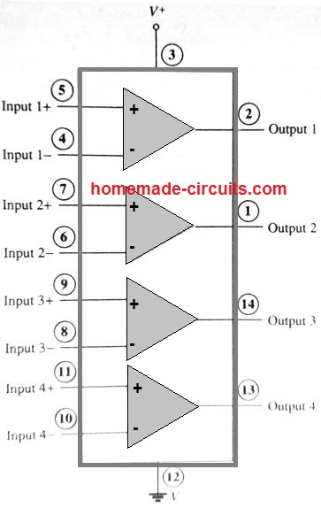
Just like any other comparator, each comparator block has a couple of inputs, and one output. When the IC is powered by applying voltage across the Vcc, and ground supply pins, it powers all the comparators together. So even if a single comparator is used, all the other 3 would be consuming some power.
All the comparator have exactly identical characteristics, therefore we can analyze any one of these to learn the basic comparator function.
When a positive differential input is applied across the input terminals, meaning when the difference between the applied signals is positive, it turns the output transistor OFF. This causes the output to show an open circuit, or a floating open.
When the differential input is negative, meaning when the difference between the applied signals at the input pins is negative, it turns ON the output transistor of the comparator, which causes the output pin of the comparator to turn negative, or at V- potential.
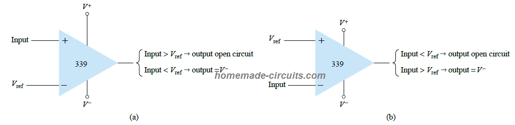
Referring to the figure above, we can understand that when the non-inverting (+) input of the IC is used as the reference pin, a voltage lower than this reference at the inverting input pin (-) will result in the output of the comparator to become open. On the other hand, if the (-) is used as the reference pin, a voltage level at the (+) input higher than the reference will cause the output to turn negative or at V-
In order to learn how the IC 339 works like a comparator, the following example shows the IC as a zero crossing detector.
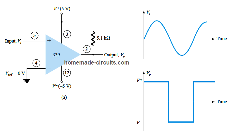
The moment the input signal rises above 0 V, the output is turned high at V+ level. The output is turned OFF at V- only while the input is held below 0 V.
As explained previously, the reference level does not need to be 0 V, it can be changed to any other desired level. Additionally, you can also use the other input pin (+) as the reference pin, and the (-) input pin as the signal input pin for accepting the varying input signal.
Advantage of having a Floating Output in Comparator ICs
As discussed in the previous explanations, comparators output is switched through BJT which have an open collector as the output. This gives the advantage of connecting the outputs of two comparators from the IC 339 directly just like an OR gate.
A nice example of a window comparator circuit can be seen below. Here two IC 339 comparators blocks are configured with a single common input signal, and the outputs are joined like OR gate.
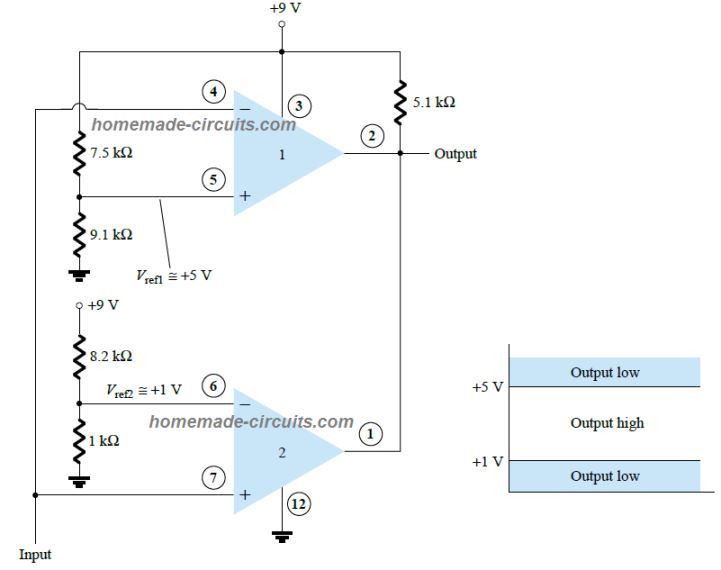
The output of the respective comparators go low whenever the input signal crosses either the lower set threshold or the upper set threshold, thus enabling the user to know when the signal is out of the set window level.
A window comparator can be used for useful applications such as high low voltage protector circuit, and solar tracker circuit etc.
Conclusion
From the above explanations, I have explained that:
Comparators are basically units having two complementing inputs, and one responsive output. The output turns high or low when the voltage level on one of the inputs goes higher or lower than the other input, depending upon which input is used as the reference or at a fixed voltage level.
Although an op amp can be also used like a comparator, specialized comparator ICs are better designed to work like comparators.
Dedicated comparator ICs like LM311, LM339 are specially designed for comparator application, with faster response and a flexible high current output capability.
If you have any related questions, please feel free to ask them through the comment box below.

Questions & Answers
Sir… I want to build a circuit, where a decreasing signal is fed, only at one point it suddenly increases and after reaching a peak it decreases, using an op-amp i want to detect the positive slope that is occurring, and to light up an LED or a relay switch, when the voltage as reached its peak, and i have to display the value of the peak. Can you guide me in creating this circuit, if possible can share circuit diagram, component values, any form guidance will really be helpful
Hi Joe, I think you can try the following idea:
sir….any other circuit involving a differentiator and comparator which drives the relay switch
If you connect a transistor relay driver stage at the output of the opamp, you can operate a relay at the collector side of the transistor.
I want to get the circuit which can be connected in series with the feeder (DC Load). it compare the input current and output current to load and if there is difference between input and output current it glow the led which means the circuit has another path of current.
You can modify the following comparator circuit to suit your needs:
Hello sir Swagatam good afternoon, my name is Carlos and I am interested in a circuit. I need a circuit what active a relay with mv.. For example 45 to 100mv and with lm358 can you do it? . Thanks a lot.
Hi Carlos, you just have use any op amp like 741, attach a 10K preset to its pin#2, and apply the mV signal to pin#3. Preset outer pins will connect with the DC supply lines, and the center pin of the preset will connect with the pin#2 of the IC. Next, apply 100mV positive signal to pin#3, adjust the preset until the output is triggered high.
Thank you for this article sir… It’s been very helpful… You are really amazing..
Thank you Fredstev, glad you liked it!
Great article, now I understand a lot more about the comparator IC
Thank you for your feedback, glad it helped you to understand the subject!
Thank you for that circuit! It is much simpler than I did myself (and will probably work better!) I assume the hysteresis occurs by the feedback from pin 6 to pin 3 through the diode. Is the “turn off” level set as a voltage divider between the 10K resister on the base of BC547 and the variable 10K tied to pin 3? Thanks again. I will write you when I get a circuit built and checked.
You are welcome, yes the hysteresis level is controlled by the 10k feedback preset between pin6 and pin3 of the op amp, and this preset also sets the lower voltage turn ON threshold at which the op amp output reverts to the original situation.
The turn OFF threshold is adjusted by the other 10k preset associated with the pin2 of the op amp
I need a simple comparitor circuit to “latch” a fan on when the reference voltage rises above some set value. It is for a CO2 controller for an exhaust fan in a small church I belong to. The CO2 level signal is 0 to +5 V. but varies somewhat irregularly, maybe +-0.1volts, as the air flows over the sensor element. Once the CO2 level is once triggered it needs to keep the fan on until a lower voltage is sensed at which time it must turn the fan back off. Both upper and lower trigger levels need to be set by potentiometers. My circuit used a mechanical relay which changed the turn off trigger level once fired. My circuit worked OK , but not being an electronic engineer it failed after a short period. I’m not sure what failed. It oscillated, causing the exhaust fan to start and stop quickly. Are you interested in helping me?
You can try the following concept, you may have to tweak a few of the parameters according to your specific implementation, and results:
Op Amp need compensation under certain conditions – capacitive loads, near unity gain. A simple pole is often builtin which results in 90 degree phase margin and a sluggish large signal response.